Ideal Esprit HE Combi Boilers 24,30,35 User Guide - BHL.co.uk
Ideal Esprit HE Combi Boilers 24,30,35 User Guide - BHL.co.uk
Ideal Esprit HE Combi Boilers 24,30,35 User Guide - BHL.co.uk

You also want an ePaper? Increase the reach of your titles
YUMPU automatically turns print PDFs into web optimized ePapers that Google loves.
BOILER CONTROL INTERLOCKS<br />
<strong>Ideal</strong> Stelrad Group re<strong>co</strong>mmend that heating systems<br />
utilising full thermostatic radiator valve <strong>co</strong>ntrol of temperature<br />
in individual rooms should also be fitted with a room<br />
thermostat <strong>co</strong>ntrolling the temperature in a space served by<br />
radiators not fitted with such a valve as stated in BS. 5449.<br />
Central heating system <strong>co</strong>ntrols should be installed to<br />
ensure the boiler is switched off when there is no demand<br />
for heating or hot water.<br />
GENERAL<br />
ELECTRICAL SUPPLY<br />
WARNING.<br />
This appliance must be earthed.<br />
Wiring external to the appliance MUST be in ac<strong>co</strong>rdance with<br />
the current I.E.E. (BS.7671) Wiring Regulations and any local<br />
regulations which apply. For IE reference should be made to<br />
the current ETCI rules for electrical installations.<br />
The point of <strong>co</strong>nnection to the mains should be readily<br />
accessible and adjacent to the boiler.<br />
N.B. T<strong>HE</strong> FAN VOLTAGE IS 325VDC<br />
When thermostatic radiator valves are used, the space<br />
heating temperature <strong>co</strong>ntrol over a living / dining area or<br />
hallway having a heating requirement of at least 10% of the<br />
boiler heat output should be achieved using a room<br />
thermostat, whilst other rooms are individually <strong>co</strong>ntrolled by<br />
thermostatic radiator valves. However, if the system employs<br />
thermostatic radiator valves on all radiators, or two port<br />
valves without end switches, then a bypass circuit is<br />
in<strong>co</strong>rporated within the boiler to ensure a flow of water<br />
should all valves be in the closed position.<br />
CONDENSATE DRAIN Refer to Frames 21 & 49.<br />
A <strong>co</strong>ndensate drain is provided on the boiler. This drain must<br />
be <strong>co</strong>nnected to a drainage point on site. All pipework and<br />
fittings in the <strong>co</strong>ndensate drainage system MUST be made of<br />
plastic - no other materials may be used.<br />
IMPORTANT.<br />
Any external runs must be insulated.<br />
The drain outlet on the boiler is standard 21.5mm (3/4”)<br />
overflow pipe.<br />
3 SYSTEM REQUIREMENTS - Central Heating<br />
Notes<br />
a. The method of filling, refilling, topping up or flushing<br />
sealed primary hot water circuits from the mains via a<br />
temporary hose <strong>co</strong>nnection is only allowed if acceptable<br />
to the local water authority.<br />
b. Antifreeze fluid, <strong>co</strong>rrosion and scale inhibitor fluids<br />
suitable for use with boilers having aluminium heat<br />
exchangers may be used in the central heating system.<br />
Advice should be sought from a local water treatment<br />
<strong>co</strong>mpany.<br />
General<br />
1. The installation must <strong>co</strong>mply with all relevant national and<br />
local regulations.<br />
2. The installation should be designed to work with flow<br />
temperatures of up to 82 o C.<br />
3. All <strong>co</strong>mponents of the system must be suitable for a working<br />
pressure of 3 bar and temperature of 110 o C. Extra care should<br />
be taken in making all <strong>co</strong>nnections so that the risk of leakage<br />
is minimised.<br />
The following <strong>co</strong>mponents are in<strong>co</strong>rporated within the<br />
appliance:<br />
a. Circulating pump.<br />
b. Safety valve, with a non-adjustable preset lift pressure of<br />
3 bar.<br />
c. Pressure gauge, <strong>co</strong>vering a range of 0 to 6 bar.<br />
d. An 8-litre expansion vessel, with an initial charge pressure<br />
of 1.0 bar.<br />
4. 'Make-up' Water. Provision must be made for replacing<br />
water loss from the system, either :<br />
a. From a manually filled 'make-up' vessel with a readily<br />
visible water level. The vessel should be mounted at<br />
least 150mm above the highest point of the system and<br />
be <strong>co</strong>nnected through a non-return valve to the system,<br />
fitted at least 150mm below the 'make-up' vessel on the<br />
return side of the radiators.<br />
<strong>Esprit</strong> - Installation and Servicing<br />
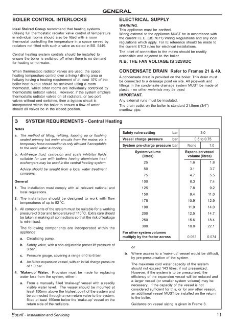
Safety valve setting bar 3.0<br />
Vessel charge pressure bar 0.5 to 0.75<br />
System pre-charge pressure bar None 1.0<br />
System volume<br />
Expansion vessel<br />
(litres)<br />
volume (litres)<br />
25 1.6 1.8<br />
50 3.1 3.7<br />
75 4.7 5.5<br />
100 6.3 7.4<br />
125 7.8 9.2<br />
150 9.4 11.0<br />
175 10.9 12.9<br />
190 11.9 14.0<br />
200 12.5 14.7<br />
250 15.6 18.4<br />
<strong>30</strong>0 18.8 22.1<br />
For other system volumes<br />
multiply by the factor across 0.063 0.074<br />
or<br />
b. Where access to a 'make-up' vessel would be difficult,<br />
by pre-pressurisation of the system.<br />
The maximum <strong>co</strong>ld water capacity of the system<br />
should not exceed 143 litres, if not pressurized.<br />
However, if the system is to be pressurized, the<br />
efficiency of the expansion vessel will be reduced and<br />
a larger vessel (or smaller system volume) may be<br />
necessary. If the capacity of the vessel is not<br />
<strong>co</strong>nsidered sufficient for this, or for any other reason,<br />
an additional vessel MUST be installed on the return<br />
to the boiler.<br />
Guidance on vessel sizing is given in Frame 3.<br />
11