Ideal Esprit HE Combi Boilers 24,30,35 User Guide - BHL.co.uk
Ideal Esprit HE Combi Boilers 24,30,35 User Guide - BHL.co.uk
Ideal Esprit HE Combi Boilers 24,30,35 User Guide - BHL.co.uk

You also want an ePaper? Increase the reach of your titles
YUMPU automatically turns print PDFs into web optimized ePapers that Google loves.
52 REPLACEMENT OF COMPONENTS<br />
SERVICING<br />
GENERAL<br />
When replacing ANY <strong>co</strong>mponent<br />
1. Isolate the electricity supply.<br />
2. Turn off the gas supply.<br />
3. Remove the boiler front panel. Refer to Frame 45.<br />
After replacing ANY <strong>co</strong>mponent check operation of the boiler,<br />
including gas tightness, gas rate and <strong>co</strong>mbustion test.<br />
IMPORTANT.<br />
When work is <strong>co</strong>mplete, the front panel, if removed, must be<br />
<strong>co</strong>rrectly refitted - ensuring that a good seal is made.<br />
Notes.<br />
1. In order to assist fault finding, the <strong>co</strong>ntrol panel has an<br />
LED diagnostic display. The key to boiler fault <strong>co</strong>nditions<br />
is shown in Frame 84.<br />
2. In order to replace some <strong>co</strong>mponents it is necessary to<br />
drain the boiler. Refer to Frame 72.<br />
T<strong>HE</strong> BOILER MUST NOT BE OPERATED WITHOUT T<strong>HE</strong> FRONT PANEL FITTED<br />
53 DRY FIRE T<strong>HE</strong>RMISTOR REPLACEMENT<br />
1. Refer to Frame 52.<br />
SERVICING<br />
2. Drain down the boiler. Refer to Frame 72.<br />
3. Unplug the electrical lead.<br />
4. Unscrew the thermistor.<br />
5. Fit the new thermistor using the sealing washer<br />
provided.<br />
6. Reassemble in the reverse order.<br />
7. Check the operation of the boiler. Refer to Frame 52 .<br />
nm8766<br />
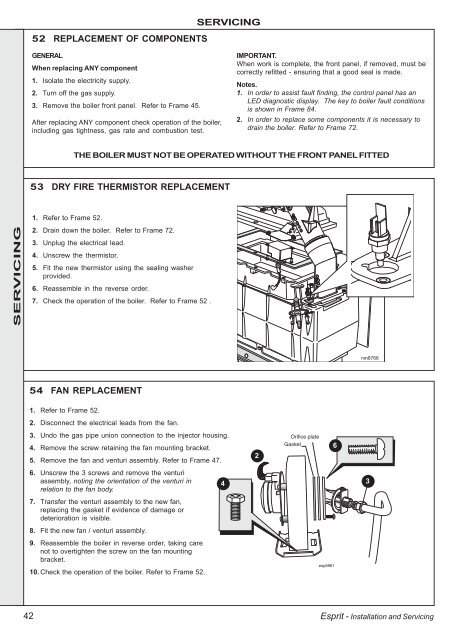
54 FAN REPLACEMENT<br />
1. Refer to Frame 52.<br />
2. Dis<strong>co</strong>nnect the electrical leads from the fan.<br />
3. Undo the gas pipe union <strong>co</strong>nnection to the injector housing.<br />
4. Remove the screw retaining the fan mounting bracket.<br />
5. Remove the fan and venturi assembly. Refer to Frame 47.<br />
2<br />
Orifice plate<br />
Gasket<br />
6<br />
6. Unscrew the 3 screws and remove the venturi<br />
assembly, noting the orientation of the venturi in<br />
relation to the fan body.<br />
4<br />
3<br />
7. Transfer the venturi assembly to the new fan,<br />
replacing the gasket if evidence of damage or<br />
deterioration is visible.<br />
8. Fit the new fan / venturi assembly.<br />
9. Reassemble the boiler in reverse order, taking care<br />
not to overtighten the screw on the fan mounting<br />
bracket.<br />
10. Check the operation of the boiler. Refer to Frame 52.<br />
esp8861<br />
42<br />
<strong>Esprit</strong> - Installation and Servicing