Ideal Esprit HE Combi Boilers 24,30,35 User Guide - BHL.co.uk
Ideal Esprit HE Combi Boilers 24,30,35 User Guide - BHL.co.uk
Ideal Esprit HE Combi Boilers 24,30,35 User Guide - BHL.co.uk

Create successful ePaper yourself
Turn your PDF publications into a flip-book with our unique Google optimized e-Paper software.
INSTALLATION<br />
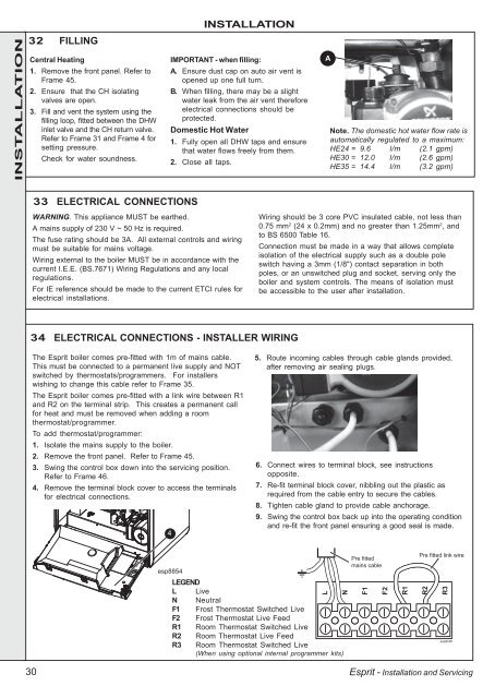
32 FILLING<br />
Central Heating<br />
1. Remove the front panel. Refer to<br />
Frame 45.<br />
2. Ensure that the CH isolating<br />
valves are open.<br />
3. Fill and vent the system using the<br />
filling loop, fitted between the DHW<br />
inlet valve and the CH return valve.<br />
Refer to Frame 31 and Frame 4 for<br />
setting pressure.<br />
Check for water soundness.<br />
INSTALLATION<br />
IMPORTANT - when filling:<br />
A. Ensure dust cap on auto air vent is<br />
opened up one full turn.<br />
B. When filling, there may be a slight<br />
water leak from the air vent therefore<br />
electrical <strong>co</strong>nnections should be<br />
protected.<br />
Domestic Hot Water<br />
1. Fully open all DHW taps and ensure<br />
that water flows freely from them.<br />
2. Close all taps.<br />
A<br />
Note. The domestic hot water flow rate is<br />
automatically regulated to a maximum:<br />
<strong>HE</strong><strong>24</strong> = 9.6 l/m (2.1 gpm)<br />
<strong>HE</strong><strong>30</strong> = 12.0 l/m (2.6 gpm)<br />
<strong>HE</strong><strong>35</strong> = 14.4 l/m (3.2 gpm)<br />
33 ELECTRICAL CONNECTIONS<br />
WARNING. This appliance MUST be earthed.<br />
A mains supply of 2<strong>30</strong> V ~ 50 Hz is required.<br />
The fuse rating should be 3A. All external <strong>co</strong>ntrols and wiring<br />
must be suitable for mains voltage.<br />
Wiring external to the boiler MUST be in ac<strong>co</strong>rdance with the<br />
current I.E.E. (BS.7671) Wiring Regulations and any local<br />
regulations.<br />
For IE reference should be made to the current ETCI rules for<br />
electrical installations.<br />
Wiring should be 3 <strong>co</strong>re PVC insulated cable, not less than<br />
0.75 mm 2 (<strong>24</strong> x 0.2mm) and no greater than 1.25mm 2 , and<br />
to BS 6500 Table 16.<br />
Connection must be made in a way that allows <strong>co</strong>mplete<br />
isolation of the electrical supply such as a double pole<br />
switch having a 3mm (1/8") <strong>co</strong>ntact separation in both<br />
poles, or an unswitched plug and socket, serving only the<br />
boiler and system <strong>co</strong>ntrols. The means of isolation must<br />
be accessible to the user after installation.<br />
34 ELECTRICAL CONNECTIONS - INSTALLER WIRING<br />
The <strong>Esprit</strong> boiler <strong>co</strong>mes pre-fitted with 1m of mains cable.<br />
This must be <strong>co</strong>nnected to a permanent live supply and NOT<br />
switched by thermostats/programmers. For installers<br />
wishing to change this cable refer to Frame <strong>35</strong>.<br />
The <strong>Esprit</strong> boiler <strong>co</strong>mes pre-fitted with a link wire between R1<br />
and R2 on the terminal strip. This creates a permanent call<br />
for heat and must be removed when adding a room<br />
thermostat/programmer.<br />
To add thermostat/programmer:<br />
1. Isolate the mains supply to the boiler.<br />
2. Remove the front panel. Refer to Frame 45.<br />
3. Swing the <strong>co</strong>ntrol box down into the servicing position.<br />
Refer to Frame 46.<br />
4. Remove the terminal block <strong>co</strong>ver to access the terminals<br />
for electrical <strong>co</strong>nnections.<br />
4<br />
5. Route in<strong>co</strong>ming cables through cable glands provided,<br />
after removing air sealing plugs.<br />
6. Connect wires to terminal block, see instructions<br />
opposite.<br />
7. Re-fit terminal block <strong>co</strong>ver, nibbling out the plastic as<br />
required from the cable entry to secure the cables.<br />
8. Tighten cable gland to provide cable anchorage.<br />
9. Swing the <strong>co</strong>ntrol box back up into the operating <strong>co</strong>ndition<br />
and re-fit the front panel ensuring a good seal is made.<br />
esp8854<br />
LEGEND<br />
L Live<br />
N Neutral<br />
F1 Frost Thermostat Switched Live<br />
F2 Frost Thermostat Live Feed<br />
R1 Room Thermostat Switched Live<br />
R2 Room Thermostat Live Feed<br />
R3 Room Thermostat Switched Live<br />
(When using optional internal programmer kits)<br />
L<br />
N<br />
Pre fitted<br />
mains cable<br />
F1<br />
F2<br />
R1<br />
Pre fitted link wire<br />
R2<br />
R3<br />
esp9189<br />
<strong>30</strong><br />
<strong>Esprit</strong> - Installation and Servicing