- Page 1:
www.GetPedia.com
- Page 4 and 5:
Copyright © 2003 by The McGraw-Hil
- Page 6 and 7:
This page intentionally left blank.
- Page 8 and 9:
vi Contents Commutation 34 Installa
- Page 10 and 11:
viii Contents Chapter 4 Wheeled Veh
- Page 12 and 13:
x Contents Industrial Robots 258 In
- Page 14 and 15:
xii Introduction a unique robot. Wh
- Page 16 and 17:
xiv Introduction outdoor and indoor
- Page 18 and 19:
xvi Introduction Rapid prototyping
- Page 20 and 21:
xviii Introduction Because the phot
- Page 22 and 23:
xx Introduction Meanwhile, the opaq
- Page 24 and 25:
xxii Introduction Laminated-Object
- Page 26 and 27:
xxiv Introduction Figure 5 Fused De
- Page 28 and 29:
xxvi Introduction ton. This process
- Page 30 and 31:
xxviii Introduction Figure 8 Ballis
- Page 32 and 33:
xxx Introduction laser fusing of ce
- Page 34 and 35:
xxxii Introduction material to form
- Page 36 and 37:
This page intentionally left blank.
- Page 38 and 39:
This page intentionally left blank.
- Page 40 and 41:
This page intentionally left blank.
- Page 42 and 43:
4 Chapter 1 Motor and Motion Contro
- Page 44 and 45:
6 Chapter 1 Motor and Motion Contro
- Page 46 and 47:
8 Chapter 1 Motor and Motion Contro
- Page 48 and 49:
10 Chapter 1 Motor and Motion Contr
- Page 50 and 51:
12 Chapter 1 Motor and Motion Contr
- Page 52 and 53:
14 Chapter 1 Motor and Motion Contr
- Page 54 and 55:
16 Chapter 1 Motor and Motion Contr
- Page 56 and 57:
18 Chapter 1 Motor and Motion Contr
- Page 58 and 59:
20 Chapter 1 Motor and Motion Contr
- Page 60 and 61:
22 Chapter 1 Motor and Motion Contr
- Page 62 and 63:
24 Chapter 1 Motor and Motion Contr
- Page 64 and 65:
26 Chapter 1 Motor and Motion Contr
- Page 66 and 67:
28 Chapter 1 Motor and Motion Contr
- Page 68 and 69:
30 Chapter 1 Motor and Motion Contr
- Page 70 and 71:
32 Chapter 1 Motor and Motion Contr
- Page 72 and 73:
34 Chapter 1 Motor and Motion Contr
- Page 74 and 75:
36 Chapter 1 Motor and Motion Contr
- Page 76 and 77:
38 Chapter 1 Motor and Motion Contr
- Page 78 and 79:
40 Chapter 1 Motor and Motion Contr
- Page 80 and 81:
42 Chapter 1 Motor and Motion Contr
- Page 82 and 83:
44 Chapter 1 Motor and Motion Contr
- Page 84 and 85:
46 Chapter 1 Motor and Motion Contr
- Page 86 and 87:
48 Chapter 1 Motor and Motion Contr
- Page 88 and 89:
50 Chapter 1 Motor and Motion Contr
- Page 90 and 91:
52 Chapter 1 Motor and Motion Contr
- Page 92 and 93:
54 Chapter 1 Motor and Motion Contr
- Page 94 and 95:
56 Chapter 1 Motor and Motion Contr
- Page 96 and 97:
58 Chapter 1 Motor and Motion Contr
- Page 98 and 99:
60 Chapter 1 Motor and Motion Contr
- Page 100 and 101:
62 Chapter 1 Motor and Motion Contr
- Page 102 and 103:
64 Chapter 1 Motor and Motion Contr
- Page 104 and 105:
66 Chapter 1 Motor and Motion Contr
- Page 106 and 107:
68 Chapter 1 Motor and Motion Contr
- Page 108 and 109:
This page intentionally left blank.
- Page 110 and 111:
72 Chapter 2 Indirect Power Transfe
- Page 112 and 113:
74 Chapter 2 Indirect Power Transfe
- Page 114 and 115:
76 Chapter 2 Indirect Power Transfe
- Page 116 and 117:
78 Chapter 2 Indirect Power Transfe
- Page 118 and 119:
80 Chapter 2 Indirect Power Transfe
- Page 120 and 121:
82 Chapter 2 Indirect Power Transfe
- Page 122 and 123:
84 Chapter 2 Indirect Power Transfe
- Page 124 and 125:
86 Chapter 2 Indirect Power Transfe
- Page 126 and 127:
88 Chapter 2 Indirect Power Transfe
- Page 128 and 129:
90 Chapter 2 Indirect Power Transfe
- Page 130 and 131:
92 Chapter 2 Indirect Power Transfe
- Page 132 and 133: 94 Chapter 2 Indirect Power Transfe
- Page 134 and 135: 96 Chapter 2 Indirect Power Transfe
- Page 136 and 137: 98 Chapter 2 Indirect Power Transfe
- Page 138 and 139: 100 Chapter 2 Indirect Power Transf
- Page 140 and 141: 102 Chapter 2 Indirect Power Transf
- Page 142 and 143: 104 Chapter 2 Indirect Power Transf
- Page 144 and 145: This page intentionally left blank.
- Page 146 and 147: This page intentionally left blank.
- Page 148 and 149: 110 Chapter 3 Direct Power Transfer
- Page 150 and 151: 112 Chapter 3 Direct Power Transfer
- Page 152 and 153: 114 Chapter 3 Direct Power Transfer
- Page 154 and 155: 116 Chapter 3 Direct Power Transfer
- Page 156 and 157: 118 Chapter 3 Direct Power Transfer
- Page 158 and 159: 120 Chapter 3 Direct Power Transfer
- Page 160 and 161: 122 Chapter 3 Direct Power Transfer
- Page 162 and 163: 124 Chapter 3 Direct Power Transfer
- Page 164 and 165: This page intentionally left blank.
- Page 166 and 167: This page intentionally left blank.
- Page 168 and 169: 130 Chapter 4 Wheeled Vehicle Suspe
- Page 170 and 171: 132 Chapter 4 Wheeled Vehicle Suspe
- Page 172 and 173: 134 Chapter 4 Wheeled Vehicle Suspe
- Page 174 and 175: 136 Chapter 4 Wheeled Vehicle Suspe
- Page 176 and 177: 138 Chapter 4 Wheeled Vehicle Suspe
- Page 178 and 179: 140 Chapter 4 Wheeled Vehicle Suspe
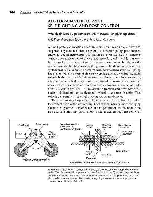
- Page 180 and 181: 142 Chapter 4 Wheeled Vehicle Suspe
- Page 184 and 185: 146 Chapter 4 Wheeled Vehicle Suspe
- Page 186 and 187: 148 Chapter 4 Wheeled Vehicle Suspe
- Page 188 and 189: 150 Chapter 4 Wheeled Vehicle Suspe
- Page 190 and 191: 152 Chapter 4 Wheeled Vehicle Suspe
- Page 192 and 193: 154 Chapter 4 Wheeled Vehicle Suspe
- Page 194 and 195: 156 Chapter 4 Wheeled Vehicle Suspe
- Page 196 and 197: 158 Chapter 4 Wheeled Vehicle Suspe
- Page 198 and 199: This page intentionally left blank.
- Page 200 and 201: This page intentionally left blank.
- Page 202 and 203: 164 Chapter 5 Tracked Vehicle Suspe
- Page 204 and 205: 166 Chapter 5 Tracked Vehicle Suspe
- Page 206 and 207: 168 Chapter 5 Tracked Vehicle Suspe
- Page 208 and 209: 170 Chapter 5 Tracked Vehicle Suspe
- Page 210 and 211: 172 Chapter 5 Tracked Vehicle Suspe
- Page 212 and 213: 174 Chapter 5 Tracked Vehicle Suspe
- Page 214 and 215: 176 Chapter 5 Tracked Vehicle Suspe
- Page 216 and 217: 178 Chapter 5 Tracked Vehicle Suspe
- Page 218 and 219: 180 Chapter 5 Tracked Vehicle Suspe
- Page 220 and 221: 182 Chapter 5 Tracked Vehicle Suspe
- Page 222 and 223: 184 Chapter 5 Tracked Vehicle Suspe
- Page 224 and 225: This page intentionally left blank.
- Page 226 and 227: This page intentionally left blank.
- Page 228 and 229: 190 Chapter 6 Steering History In t
- Page 230 and 231: 192 Chapter 6 Steering History and
- Page 232 and 233:
194 Chapter 6 Steering History Figu
- Page 234 and 235:
196 Chapter 6 Steering History Figu
- Page 236 and 237:
198 Chapter 6 Steering History forc
- Page 238 and 239:
This page intentionally left blank.
- Page 240 and 241:
202 Chapter 7 Walkers when crossing
- Page 242 and 243:
204 Chapter 7 Walkers Figure 7-1 On
- Page 244 and 245:
206 Chapter 7 Walkers Figure 7-4 Tw
- Page 246 and 247:
208 Chapter 7 Walkers and the relat
- Page 248 and 249:
210 Chapter 7 Walkers Figure 7-10 E
- Page 250 and 251:
212 Chapter 7 Walkers Figure 7-12 T
- Page 252 and 253:
214 Chapter 7 Walkers ROLLER-WALKER
- Page 254 and 255:
216 Chapter 7 Walkers Walkers have
- Page 256 and 257:
This page intentionally left blank.
- Page 258 and 259:
220 Chapter 8 Pipe Crawlers and Oth
- Page 260 and 261:
222 Chapter 8 Pipe Crawlers and Oth
- Page 262 and 263:
224 Chapter 8 Pipe Crawlers and Oth
- Page 264 and 265:
226 Chapter 8 Pipe Crawlers and Oth
- Page 266 and 267:
This page intentionally left blank.
- Page 268 and 269:
230 Chapter 9 Comparing Locomotion
- Page 270 and 271:
232 Chapter 9 Comparing Locomotion
- Page 272 and 273:
234 Chapter 9 Comparing Locomotion
- Page 274 and 275:
236 Chapter 9 Comparing Locomotion
- Page 276 and 277:
This page intentionally left blank.
- Page 278 and 279:
This page intentionally left blank.
- Page 280 and 281:
242 Chapter 10 Manipulator Geometri
- Page 282 and 283:
244 Chapter 10 Manipulator Geometri
- Page 284 and 285:
246 Chapter 10 Manipulator Geometri
- Page 286 and 287:
248 Chapter 10 Manipulator Geometri
- Page 288 and 289:
250 Chapter 10 Manipulator Geometri
- Page 290 and 291:
252 Chapter 10 Manipulator Geometri
- Page 292 and 293:
254 Chapter 10 Manipulator Geometri
- Page 294 and 295:
256 Chapter 10 Manipulator Geometri
- Page 296 and 297:
258 Chapter 10 Manipulator Geometri
- Page 298 and 299:
260 Chapter 10 Manipulator Geometri
- Page 300 and 301:
262 Chapter 10 Manipulator Geometri
- Page 302 and 303:
This page intentionally left blank.
- Page 304 and 305:
266 Chapter 11 Proprioceptive and E
- Page 306 and 307:
268 Chapter 11 Proprioceptive and E
- Page 308 and 309:
270 Chapter 11 Proprioceptive and E
- Page 310 and 311:
272 Chapter 11 Proprioceptive and E
- Page 314 and 315:
276 Chapter 11 Proprioceptive and E
- Page 316 and 317:
278 Chapter 11 Proprioceptive and E
- Page 318 and 319:
280 Chapter 11 Proprioceptive and E
- Page 320 and 321:
282 Chapter 11 Proprioceptive and E
- Page 322 and 323:
284 Chapter 11 Proprioceptive and E
- Page 324 and 325:
286 Chapter 11 Proprioceptive and E
- Page 326 and 327:
288 Chapter 11 Proprioceptive and E
- Page 328 and 329:
This page intentionally left blank.
- Page 330 and 331:
292 Index CAM-LEM, Inc., xxiii camm
- Page 332 and 333:
294 Index (ground pressure cont.) a
- Page 334 and 335:
296 Index (mobility systems cont.)
- Page 336 and 337:
298 Index shear pin torque limiters
- Page 338:
About the Author Paul E. Sandin is