GA-EX58-UD3R - Hardware
GA-EX58-UD3R - Hardware
GA-EX58-UD3R - Hardware

You also want an ePaper? Increase the reach of your titles
YUMPU automatically turns print PDFs into web optimized ePapers that Google loves.
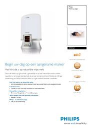
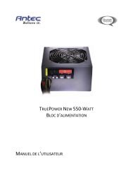
13) F_PANEL (Front Panel Header)<br />
Connect the power switch, reset switch, speaker and system status indicator on the chassis front<br />
panel to this header according to the pin assignments below. Note the positive and negative pins<br />
before connecting the cables.<br />
Message/Power/<br />
Sleep LED<br />
Power<br />
Switch<br />
Speaker<br />
MSG+<br />
PW+<br />
SPEAK+<br />
20<br />
19<br />
HD+<br />
RES-<br />
NC<br />
SPEAK-<br />
HD-<br />
RES+<br />
MSG-<br />
PW-<br />
2<br />
1<br />
Hard Drive<br />
Activity LED<br />
Reset<br />
Switch<br />
• MSG (Message/Power/Sleep LED, Yellow):<br />
System Status LED Connects to the power status indicator on the chassis front panel. The<br />
S0<br />
On LED is on when the system is operating. The LED keeps blinking when<br />
S1<br />
Blinking the system is in S1 sleep state. The LED is off when the system is in<br />
S3/S4/S5 Off S3/S4 sleep state or powered off (S5).<br />
• PW (Power Switch, Red):<br />
Connects to the power switch on the chassis front panel. You may configure the way to turn off<br />
your system using the power switch (refer to Chapter 2, "BIOS Setup," "Power Management<br />
Setup," for more information).<br />
• SPEAK (Speaker, Orange):<br />
Connects to the speaker on the chassis front panel. The system reports system startup status<br />
by issuing a beep code. One single short beep will be heard if no problem is detected at system<br />
startup. If a problem is detected, the BIOS may issue beeps in different patterns to indicate the<br />
problem. Refer to Chapter 5, "Troubleshooting," for information about beep codes.<br />
• HD (Hard Drive Activity LED, Blue)<br />
Connects to the hard drive activity LED on the chassis front panel. The LED is on when the hard<br />
drive is reading or writing data.<br />
• RES (Reset Switch, Green):<br />
Connects to the reset switch on the chassis front panel. Press the reset switch to restart the<br />
computer if the computer freezes and fails to perform a normal restart.<br />
• NC (Purple):<br />
No connection<br />
The front panel design may differ by chassis. A front panel module mainly consists of<br />
power switch, reset switch, power LED, hard drive activity LED, speaker and etc. When<br />
connecting your chassis front panel module to this header, make sure the wire assignments<br />
and the pin assignments are matched correctly.<br />
- 27 -<br />
<strong>Hardware</strong> Installation