

Catalog LV 70 2011 - Low & Medium Voltage - Siemens
Catalog LV 70 2011 - Low & Medium Voltage - Siemens
Catalog LV 70 2011 - Low & Medium Voltage - Siemens

You also want an ePaper? Increase the reach of your titles
YUMPU automatically turns print PDFs into web optimized ePapers that Google loves.
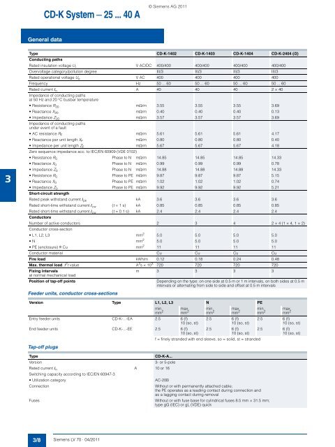
CD-K System — 25 ... 40 A<br />
© <strong>Siemens</strong> AG <strong>2011</strong><br />
General data<br />
3<br />
Type CD-K-1402 CD-K-1403 CD-K-1404 CD-K-2404 (/2)<br />
Conducting paths<br />
Rated insulation voltage U i V AC/DC 400/400 400/400 400/400 400/400<br />
Overvoltage category/pollution degree III/3 III/3 III/3 III/3<br />
Rated operational voltage U e V AC 400 400 400 400<br />
Frequency Hz 50 ... 60 50 ... 60 50 ... 60 50 ... 60<br />
Rated current I n A 40 40 40 2 × 40<br />
Impedance of conducting paths<br />
at 50 Hz and 20 °C busbar temperature<br />
• Resistance R 20 mΩ/m 3.55 3.55 3.55 3.69<br />
• Reactance X 20 mΩ/m 0.40 0.40 0.40 0.13<br />
• Impedance Z 20 mΩ/m 3.57 3.57 3.57 3.69<br />
Impedance of conducting paths<br />
under event of a fault<br />
• AC resistance R F mΩ/m 5.61 5.61 5.61 4.17<br />
• Reactance per unit length X F mΩ/m 0.80 0.80 0.80 0.40<br />
• Impedance per unit length Z F mΩ/m 5.67 5.67 5.67 4.18<br />
Zero sequence impedance acc. to IEC/EN 60909 (VDE 0102)<br />
• Resistance R 0 Phase to N mΩ/m 14.85 14.85 14.85 14.33<br />
• Reactance X 0 Phase to N mΩ/m 0.99 0.99 0.99 0.78<br />
• Impedance Z 0 Phase to N mΩ/m 14.88 14.88 14.88 14.33<br />
• Resistance R 0 Phase to PE mΩ/m 9.87 9.87 9.87 5.15<br />
• Reactance X 0 Phase to PE mΩ/m 1.02 1.02 1.02 0.74<br />
• Impedance Z 0 Phase to PE mΩ/m 9.92 9.92 9.92 5.21<br />
Short-circuit strength<br />
Rated peak withstand current I pk kA 3.6 3.6 3.6 3.6<br />
Rated short-time withstand current I cw (t = 1 s) kA 0.85 0.85 0.85 0.85<br />
Rated short-time withstand current I cw (t = 0.1 s) kA 2.4 2.4 2.4 2.4<br />
Conductors<br />
Number of active conductors 2 3 4 2 × 4 (1 × 4, 1 × 2)<br />
Conductor cross-section<br />
• L1, L2, L3 mm 2 5.0 5.0 5.0 5.0<br />
•N mm 2 5.0 5.0 5.0 5.0<br />
• PE (enclosure) r Cu mm 2 11 11 11 11<br />
Conductor material Cu Cu Cu Cu<br />
Fire load kWh/m 0.12 0.18 0.24 0.48<br />
Max. thermal load, I 2 t value A 2 s × 10 3 720 720 720 720<br />
Fixing intervals<br />
m 3 3 3 3<br />
at normal mechanical load<br />
Position of tap-off points<br />
Depending on the type: on one side at 0.5 m or 1 m intervals, on both sides at 0.5 m<br />
intervals or alternating from side to side and offset at 0.5 m intervals<br />
Feeder units, conductor cross-sections<br />
Version Type L1, L2, L3 N PE<br />
Tap-off plugs<br />
min.<br />
mm 2<br />
max.<br />
mm 2<br />
Entry feeder units CD-K-...-EA 2.5 6 (f)<br />
10 (so, st)<br />
End feeder units CD-K-...-EE 2.5 6 (f)<br />
10 (so, st)<br />
min.<br />
mm 2<br />
max.<br />
mm 2<br />
2.5 6 (f)<br />
10 (so, st)<br />
2.5 6 (f)<br />
10 (so, st)<br />
f = finely stranded with end sleeve, so = solid, st = stranded<br />
Type<br />
CD-K-A...<br />
Version<br />
3- or 5-pole<br />
Rated current I n A 10 or 16<br />
Switching capacity according to IEC/EN 60947-3<br />
• Utilization category<br />
AC-20B<br />
Connection<br />
Without or with permanently attached cable;<br />
the PE operates as a leading contact during connection and<br />
as a lagging contact during removal<br />
Fuses<br />
Without or with fuse base for cylindrical fuses 8.5 mm × 31.5 mm;<br />
type gG (IEC) or gL (VDE) quick<br />
min.<br />
mm 2<br />
max.<br />
mm 2<br />
2.5 6 (f)<br />
10 (so, st)<br />
2.5 6 (f)<br />
10 (so, st)<br />
3/8 <strong>Siemens</strong> <strong>LV</strong> <strong>70</strong> · 04/<strong>2011</strong>


