

Catalog LV 70 2011 - Low & Medium Voltage - Siemens
Catalog LV 70 2011 - Low & Medium Voltage - Siemens
Catalog LV 70 2011 - Low & Medium Voltage - Siemens

You also want an ePaper? Increase the reach of your titles
YUMPU automatically turns print PDFs into web optimized ePapers that Google loves.
CD-K System — 25 ... 40 A<br />
© <strong>Siemens</strong> AG <strong>2011</strong><br />
Configuration information<br />
■ Function<br />
Short-circuit protection<br />
The lengths of the CD busbar lines given in the guide value tables<br />
on page 3/18 and 3/19 take into account only the rated current<br />
of the connectable luminaires.<br />
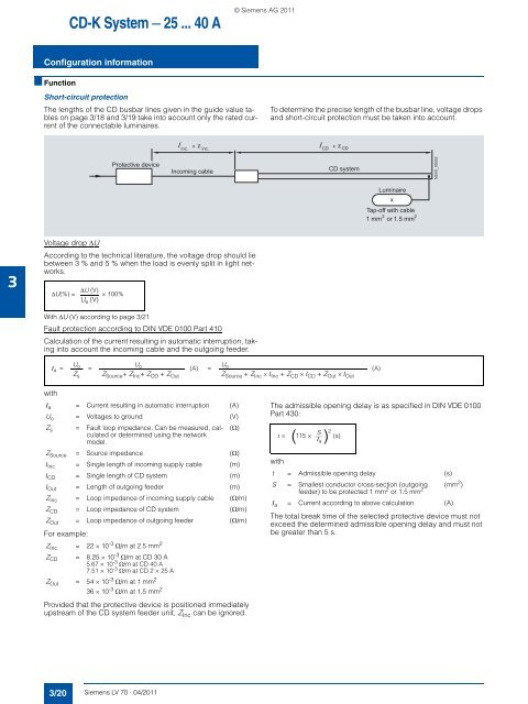
To determine the precise length of the busbar line, voltage drops<br />
and short-circuit protection must be taken into account.<br />
z<br />
inc. inc. CD CD<br />
z<br />
Protective device<br />
Incoming cable<br />
CD system<br />
NSV0_00032<br />
Luminaire<br />
x<br />
Tap-off with cable<br />
2 2<br />
1 mm or 1.5 mm<br />
3<br />
<strong>Voltage</strong> drop ΔU<br />
According to the technical literature, the voltage drop should lie<br />
between 3 % and 5 % when the load is evenly split in light networks.<br />
ΔU(%) =<br />
ΔU (V)<br />
U e (V) × 100%<br />
With ΔU (V) according to page 3/21<br />
Fault protection according to DIN VDE 0100 Part 410<br />
Calculation of the current resulting in automatic interruption, taking<br />
into account the incoming cable and the outgoing feeder.<br />
I a =<br />
U o<br />
Z s<br />
=<br />
U o<br />
Z Source + Z Inc + Z CD + Z Out<br />
(A)<br />
=<br />
U o<br />
Z Source + Z Inc × l Inc + Z CD × l CD + Z Out × l Out<br />
(A)<br />
with<br />
I a = Current resulting in automatic interruption (A)<br />
U o = <strong>Voltage</strong>s to ground (V)<br />
Z s = Fault loop impedance. Can be measured, calculated<br />
(Ω)<br />
or determined using the network<br />
model.<br />
Z Source = Source impedance (Ω)<br />
l Inc = Single length of incoming supply cable (m)<br />
l CD = Single length of CD system (m)<br />
l Out = Length of outgoing feeder (m)<br />
Z Inc = Loop impedance of incoming supply cable (Ω/m)<br />
Z CD = Loop impedance of CD system (Ω/m)<br />
Z Out = Loop impedance of outgoing feeder (Ω/m)<br />
For example:<br />
Z Inc = 22 × 10 -3 Ω/m at 2.5 mm 2<br />
Z CD = 8.25 × 10 -3 Ω/m at CD 30 A<br />
5.67 × 10 -3 Ω/m at CD 40 A<br />
7.51 × 10 -3 Ω/m at CD 2 × 25 A<br />
Z Out = 54 × 10 -3 Ω/m at 1 mm 2<br />
Provided that the protective device is positioned immediately<br />
upstream of the CD system feeder unit, Z Inc can be ignored.<br />
The admissible opening delay is as specified in DIN VDE 0100<br />
Part 430:<br />
with<br />
t = Admissible opening delay (s)<br />
S = Smallest conductor cross-section (outgoing (mm 2 )<br />
feeder) to be protected 1 mm 2 or 1.5 mm 2<br />
I a = Current according to above calculation (A)<br />
t =<br />
S<br />
I (s)<br />
( ) 115 × 2<br />
a<br />
The total break time of the selected protective device must not<br />
exceed the determined admissible opening delay and must not<br />
be greater than 5 s.<br />
3/20 <strong>Siemens</strong> <strong>LV</strong> <strong>70</strong> · 04/<strong>2011</strong>


