Complete Report - University of New South Wales
Complete Report - University of New South Wales
Complete Report - University of New South Wales

You also want an ePaper? Increase the reach of your titles
YUMPU automatically turns print PDFs into web optimized ePapers that Google loves.
Silicon Nitride Passivation <strong>of</strong> Bare, n-type Silicon Surfaces<br />
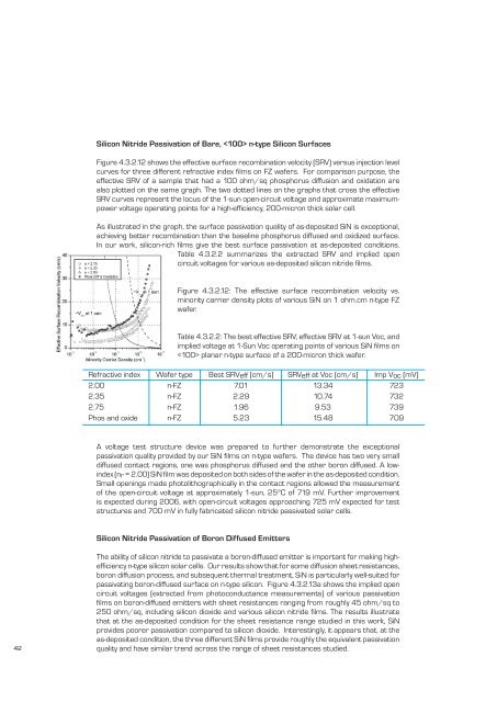
Figure 4.3.2.12 shows the effective surface recombination velocity (SRV) versus injection level<br />
curves for three different refractive index fi lms on FZ wafers. For comparison purpose, the<br />
effective SRV <strong>of</strong> a sample that had a 100 ohm/sq phosphorus diffusion and oxidation are<br />
also plotted on the same graph. The two dotted lines on the graphs that cross the effective<br />
SRV curves represent the locus <strong>of</strong> the 1-sun open-circuit voltage and approximate maximumpower<br />
voltage operating points for a high-effi ciency, 200-micron thick solar cell.<br />
As illustrated in the graph, the surface passivation quality <strong>of</strong> as-deposited SiN is exceptional,<br />
achieving better recombination than the baseline phosphorus diffused and oxidized surface.<br />
In our work, silicon-rich fi lms give the best surface passivation at as-deposited conditions.<br />
Table 4.3.2.2 summarizes the extracted SRV and implied open<br />
circuit voltages for various as-deposited silicon nitride fi lms.<br />
Figure 4.3.2.12: The effective surface recombination velocity vs.<br />
minority carrier density plots <strong>of</strong> various SiN on 1 ohm.cm n-type FZ<br />
wafer.<br />
Table 4.3.2.2: The best effective SRV, effective SRV at 1-sun Voc, and<br />
implied voltage at 1-Sun Voc operating points <strong>of</strong> various SiN fi lms on<br />
planar n-type surface <strong>of</strong> a 200-micron thick wafer.<br />
Refractive index Wafer type Best SRVeff (cm/s) SRVeff at Voc (cm/s) Imp Voc (mV)<br />
2.00 n-FZ 7.01 13.34 723<br />
2.35 n-FZ 2.29 10.74 732<br />
2.75 n-FZ 1.96 9.53 739<br />
Phos and oxide n-FZ 5.23 15.48 709<br />
A voltage test structure device was prepared to further demonstrate the exceptional<br />
passivation quality provided by our SiN fi lms on n-type wafers. The device has two very small<br />
diffused contact regions, one was phosphorus diffused and the other boron diffused. A lowindex<br />
(nr = 2.00) SiN fi lm was deposited on both sides <strong>of</strong> the wafer in the as-deposited condition.<br />
Small openings made photolithographically in the contact regions allowed the measurement<br />
<strong>of</strong> the open-circuit voltage at approximately 1-sun, 25ºC <strong>of</strong> 719 mV. Further improvement<br />
is expected during 2006, with open-circuit voltages approaching 725 mV expected for test<br />
structures and 700 mV in fully fabricated silicon nitride passivated solar cells.<br />
Silicon Nitride Passivation <strong>of</strong> Boron Diffused Emitters<br />
42<br />
The ability <strong>of</strong> silicon nitride to passivate a boron-diffused emitter is important for making higheffi<br />
ciency n-type silicon solar cells. Our results show that for some diffusion sheet resistances,<br />
boron diffusion process, and subsequent thermal treatment, SiN is particularly well-suited for<br />
passivating boron-diffused surface on n-type silicon. Figure 4.3.2.13a shows the implied open<br />
circuit voltages (extracted from photoconductance measurements) <strong>of</strong> various passivation<br />
fi lms on boron-diffused emitters with sheet resistances ranging from roughly 45 ohm/sq to<br />
250 ohm/sq, including silicon dioxide and various silicon nitride fi lms. The results illustrate<br />
that at the as-deposited condition for the sheet resistance range studied in this work, SiN<br />
provides poorer passivation compared to silicon dioxide. Interestingly, it appears that, at the<br />
as-deposited condition, the three different SiN fi lms provide roughly the equivalent passivation<br />
quality and have similar trend across the range <strong>of</strong> sheet resistances studied.