Dolby CP750 Digital Cinema Processor Manual - Projectionniste.net
Dolby CP750 Digital Cinema Processor Manual - Projectionniste.net
Dolby CP750 Digital Cinema Processor Manual - Projectionniste.net

You also want an ePaper? Increase the reach of your titles
YUMPU automatically turns print PDFs into web optimized ePapers that Google loves.
<strong>CP750</strong> Front Panel<br />
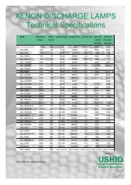
Figure 1‐3<br />
10<br />
0<br />
31/3db<br />
per step<br />
-10<br />
-20<br />
-30<br />
Output<br />
-40<br />
Level (dB)<br />
-50<br />
20 dB<br />
per step<br />
-60<br />
-70<br />
-80<br />
-90<br />
0<br />
1<br />
2 3 4 5 6 7 8<br />
9<br />
10<br />
Fader Level<br />
Figure 1-3<br />
Fader Characteristic<br />
1.2.5 USB Port<br />
The USB port is provided for connecting to a PC. You can use it either to set up the unit or<br />
to update the <strong>CP750</strong> firmware.<br />
1.2.6 <strong>Digital</strong> Input Selection Buttons<br />
When you press any of the <strong>Digital</strong> 1, <strong>Digital</strong> 2, <strong>Digital</strong> 3, or <strong>Digital</strong> 4 push buttons, that button<br />
lights up, indicating that the selected input channel is active. Pressing one of these buttons<br />
selects a specific digital input source, as shown in Table 1‐1. The <strong>CP750</strong> switches<br />
automatically between PCM and <strong>Dolby</strong> <strong>Digital</strong> bitstreams.<br />
Table 1-1<br />
<strong>Digital</strong> Input Selection Button Functionality<br />
Input Button<br />
<strong>Digital</strong> 1<br />
<strong>Digital</strong> 2<br />
<strong>Digital</strong> 3<br />
<strong>Digital</strong> 4<br />
Input Source Selected<br />
Selects the input signal from the 4xAES DIGITAL 1 connector (four‐channel<br />
pairs, 25‐pin D‐connector)<br />
Selects the input signal from the 1xAES DIGITAL 2 connector (BNC)<br />
Selects the input signal from the 1xAES DIGITAL 3 connector (BNC)<br />
Selects the input signal from the 1xAES DIGITAL 4 connector (S/PDIF optical)<br />
1.2.7 Valid Input LEDs<br />
Each digital input push button has a green Valid LED located beneath it. These LEDs light<br />
up when the <strong>CP750</strong> detects a valid signal on the respective input, whether or not the input<br />
is selected. <strong>Digital</strong> 1 and <strong>Digital</strong> 4 have valid signals in Figure 1‐1.<br />
<strong>Dolby</strong> ® <strong>CP750</strong> <strong>Digital</strong> <strong>Cinema</strong> <strong>Processor</strong> <strong>Manual</strong> 5