- Page 1: Doctoral thesis Corneal Ablation an
- Page 5 and 6: Contents Corneal Ablation and Conta
- Page 7 and 8: 2.2.1. Fitting surfaces............
- Page 9 and 10: 5.3.3. Ablation efficiency factors
- Page 11: 10.5. DISCUSSION...................
- Page 14 and 15: We thank José Antonio Sánchez-Gil
- Page 16 and 17: BOZR Back Optic Zone Radius BCVA Be
- Page 19 and 20: INTRODUCTION 1.1. MOTIVATION The fr
- Page 21 and 22: INTRODUCTION 1.2. THE OPTICAL SYSTE
- Page 23 and 24: INTRODUCTION Myopia is a very commo
- Page 25 and 26: INTRODUCTION a point focus: the dif
- Page 27 and 28: INTRODUCTION system, and tilt repre
- Page 29: INTRODUCTION term Z 0 2 stands for
- Page 33 and 34: INTRODUCTION The defocus Zernike te
- Page 35 and 36: INTRODUCTION 1.4.6.3. Internal Aber
- Page 37 and 38: INTRODUCTION 1.5.2.3. Alternating v
- Page 39 and 40: INTRODUCTION and further-more, at l
- Page 41 and 42: INTRODUCTION alcohol is used to loo
- Page 43 and 44: INTRODUCTION changes in reflectivit
- Page 45 and 46: INTRODUCTION Marcos et al. (Marcos
- Page 47 and 48: INTRODUCTION 1.7.3. Ablation effici
- Page 49 and 50: INTRODUCTION corneal surface may be
- Page 51 and 52: INTRODUCTION Algorithm design: The
- Page 53 and 54: INTRODUCTION contact lenses the fie
- Page 55 and 56: INTRODUCTION 1.10.1. Tear studies A
- Page 57 and 58: INTRODUCTION there are still many u
- Page 59 and 60: INTRODUCTION 6. Evaluation and unde
- Page 61 and 62: METHODS 2Chapter Chapter 2 - Method
- Page 63 and 64: METHODS 2.1. MEASUREMENT OF OPTICAL
- Page 65 and 66: METHODS In both profilometers, cust
- Page 67 and 68: METHODS The measurement method that
- Page 69 and 70: METHODS Fig. 2. 9. Set of points in
- Page 71 and 72: METHODS Slit lamp Scheimpflug Camer
- Page 73 and 74: METHODS representing the deviation
- Page 75 and 76: METHODS 2.2.2.2. Ablation pattern f
- Page 77 and 78: METHODS direction. These calculatio
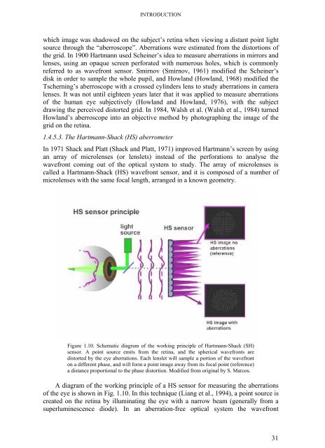
- Page 79 and 80: METHODS eye through the whole pupil
- Page 81 and 82:
METHODS (1993) power thresholds for
- Page 83 and 84:
METHODS alignment (frontal-illumina
- Page 85 and 86:
METHODS Fig. 2. 24. Example frame f
- Page 87 and 88:
METHODS 4) New image processing too
- Page 89 and 90:
METHODS Fig. 2. 28. Corrected entra
- Page 91 and 92:
METHODS Badal lens, corresponds to
- Page 93:
METHODS Each VA measurement consist
- Page 99:
REFRACTIVE SURGERY PMMA MODEL 3.1.
- Page 102 and 103:
CHAPTER 3 optimization of refractiv
- Page 104 and 105:
CHAPTER 3 These data demonstrate th
- Page 106 and 107:
CHAPTER 3 regression line, since it
- Page 108 and 109:
CHAPTER 3 Figure 3.3 shows one of t
- Page 110 and 111:
CHAPTER 3 Ablation efficiency facto
- Page 112 and 113:
CHAPTER 3 considering the same set
- Page 114 and 115:
CHAPTER 3 3.5.3 Impact of correctio
- Page 117:
ABLATION PROPERTIES OF FILOFOCON A
- Page 121 and 122:
ABLATION PROPERTIES OF FILOFOCON A
- Page 123 and 124:
ABLATION PROPERTIES OF FILOFOCON A
- Page 125 and 126:
ABLATION PROPERTIES OF FILOFOCON A
- Page 127 and 128:
ABLATION PROPERTIES OF FILOFOCON A
- Page 129 and 130:
ABLATION PROPERTIES OF FILOFOCON A
- Page 131 and 132:
ABLATION PROPERTIES OF FILOFOCON A
- Page 133:
ABLATION PROPERTIES OF FILOFOCON A
- Page 137:
OPTIMIZED LASER PLATFORMS 5.1 ABSTR
- Page 140 and 141:
CHAPTER 5 pulses. Fluence, repetiti
- Page 142 and 143:
CHAPTER 5 ablations. The slit-confo
- Page 144 and 145:
CHAPTER 5 (Anera et al., 2003): d S
- Page 146 and 147:
CHAPTER 5 asymmetries also appeared
- Page 148 and 149:
CHAPTER 5 5.3.4. Ablation patterns
- Page 150 and 151:
CHAPTER 5 a) b) : 6.5 mm c) Fig. 5.
- Page 152 and 153:
CHAPTER 5 achieve proper reflection
- Page 154 and 155:
CHAPTER 5 Both the ablation algorit
- Page 157:
HYBRID PORCINE/PLASTIC MODEL 6.1. A
- Page 160 and 161:
CHAPTER 6 6.3.1. Hybrid porcine-pla
- Page 162 and 163:
CHAPTER 6 is detected. Therefore, i
- Page 164 and 165:
CHAPTER 6 no preferential orientati
- Page 167:
ANTERIOR AND POSTERIOR CORNEAL ELEV
- Page 171 and 172:
ANTERIOR AND POSTERIOR CORNEAL ELEV
- Page 173 and 174:
ANTERIOR AND POSTERIOR CORNEAL ELEV
- Page 175 and 176:
ANTERIOR AND POSTERIOR CORNEAL ELEV
- Page 177 and 178:
ANTERIOR AND POSTERIOR CORNEAL ELEV
- Page 179 and 180:
ANTERIOR AND POSTERIOR CORNEAL ELEV
- Page 181 and 182:
ANTERIOR AND POSTERIOR CORNEAL ELEV
- Page 183:
183
- Page 187:
SOFT CONTACT LENS FITTING USING MOD
- Page 191 and 192:
SOFT CONTACT LENS FITTING USING MOD
- Page 194:
ON-EYE OPTICAL PERFORMANCE OF RIGID
- Page 198 and 199:
ON-EYE OPTICAL PERFORMANCE OF RIGID
- Page 200 and 201:
ON-EYE OPTICAL PERFORMANCE OF RIGID
- Page 202 and 203:
ON-EYE OPTICAL PERFORMANCE OF RIGID
- Page 204 and 205:
ON-EYE OPTICAL PERFORMANCE OF RIGID
- Page 206 and 207:
ON-EYE OPTICAL PERFORMANCE OF RIGID
- Page 208 and 209:
ON-EYE OPTICAL PERFORMANCE OF RIGID
- Page 210 and 211:
ON-EYE OPTICAL PERFORMANCE OF RIGID
- Page 212:
SOFT MONOFOCAL AND MULTIFOCAL CONTA
- Page 216:
SOFT MONOFOCAL AND MULTIFOCAL CONTA
- Page 220 and 221:
CORRELATION BETWEEN RADIUS AND ASPH
- Page 222 and 223:
CORRELATION BETWEEN RADIUS AND ASPH
- Page 224 and 225:
CORRELATION BETWEEN RADIUS AND ASPH
- Page 226 and 227:
CORRELATION BETWEEN RADIUS AND ASPH
- Page 228 and 229:
CORRELATION BETWEEN RADIUS AND ASPH
- Page 230:
CONCLUSIONS Conclusions This thesis
- Page 233 and 234:
CONCLUSIONS 5We have developed a pr
- Page 236:
CONCLUSIONS LIST OF METHODOLOGICAL
- Page 240 and 241:
CONCLUSIONS FUTURE RESEARCH LINES T
- Page 242 and 243:
CONCLUSIONS LIST OF PUBLICATIONS AN
- Page 244 and 245:
REFERENCES References AIZAWA, D., S
- Page 246 and 247:
REFERENCES PHOTODECOMPOSITION (APD)
- Page 248 and 249:
REFERENCES DORRONSORO, C., CANO, D.
- Page 250 and 251:
REFERENCES GISPETS, J., ARJONA, M.
- Page 252 and 253:
REFERENCES KOPF, M., YI, F., ISKAND
- Page 254 and 255:
REFERENCES MARCOS, S., DORRONSORO,
- Page 256 and 257:
REFERENCES NOVO, A., PAVLOPOULOS, G
- Page 258 and 259:
REFERENCES SAKIMOTO, T., ROSENBLATT
- Page 260:
REFERENCES WANG, L., DAI, E., KOCH,
- Page 263 and 264:
RESÚMENES pacientes reales fue com
- Page 265 and 266:
RESÚMENES experimentales de cirug
- Page 267 and 268:
RESÚMENES cada punto de las cornea
- Page 269 and 270:
RESÚMENES plástico medidas anteri
- Page 272 and 273:
RESÚMENES 8 Evaluación óptica de
- Page 274 and 275:
RESÚMENES 9 Prestaciones ópticas
- Page 276 and 277:
RESÚMENES 10 Calidad óptica y cal
- Page 278:
RESÚMENES A Correlación entre rad
- Page 281 and 282:
CONCLUSIONES clínicos. La descripc
- Page 283 and 284:
CONCLUSIONES 12 Las superficies ocu
- Page 286:
CONCLUSIONES IMPLICACIONES DE ESTA
- Page 289 and 290:
CONCLUSIONES contribuyen a la compr
- Page 291:
(y muchísimo más difícil). Me da