
Create successful ePaper yourself
Turn your PDF publications into a flip-book with our unique Google optimized e-Paper software.
Chapter 4. Record Formats<br />
Job Control Record 2 (JC2)<br />
Job Control Record 2 (JC2)<br />
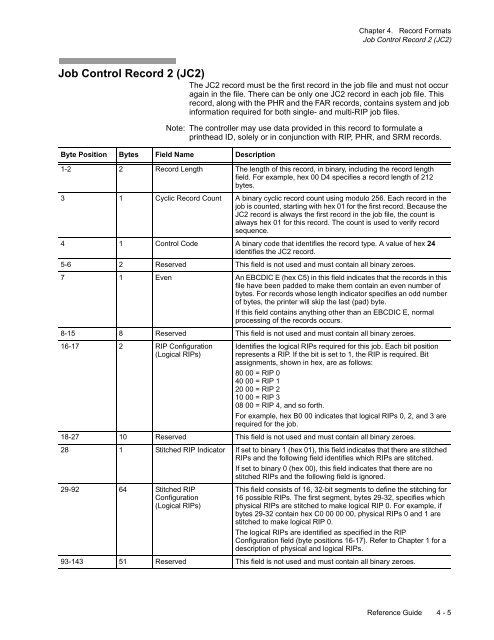
The JC2 record must be the first record in the job file and must not occur<br />
again in the file. There can be only one JC2 record in each job file. This<br />
record, along with the PHR and the FAR records, contains system and job<br />
information required for both single- and multi-RIP job files.<br />
Note: The controller may use data provided in this record to formulate a<br />
printhead ID, solely or in conjunction with RIP, PHR, and SRM records.<br />
Byte Position Bytes Field Name Description<br />
1-2 2 Record Length The length of this record, in binary, including the record length<br />
field. For example, hex 00 D4 specifies a record length of 212<br />
bytes.<br />
3 1 Cyclic Record Count A binary cyclic record count using modulo 256. Each record in the<br />
job is counted, starting with hex 01 for the first record. Because the<br />
JC2 record is always the first record in the job file, the count is<br />
always hex 01 for this record. The count is used to verify record<br />
sequence.<br />
4 1 Control Code A binary code that identifies the record type. A value of hex 24<br />
identifies the JC2 record.<br />
5-6 2 Reserved This field is not used and must contain all binary zeroes.<br />
7 1 Even An EBCDIC E (hex C5) in this field indicates that the records in this<br />
file have been padded to make them contain an even number of<br />
bytes. For records whose length indicator specifies an odd number<br />
of bytes, the printer will skip the last (pad) byte.<br />
If this field contains anything other than an EBCDIC E, normal<br />
processing of the records occurs.<br />
8-15 8 Reserved This field is not used and must contain all binary zeroes.<br />
16-17 2 RIP Configuration<br />
(Logical RIPs)<br />
Identifies the logical RIPs required for this job. Each bit position<br />
represents a RIP. If the bit is set to 1, the RIP is required. Bit<br />
assignments, shown in hex, are as follows:<br />
80 00 = RIP 0<br />
40 00 = RIP 1<br />
20 00 = RIP 2<br />
10 00 = RIP 3<br />
08 00 = RIP 4, and so forth.<br />
For example, hex B0 00 indicates that logical RIPs 0, 2, and 3 are<br />
required for the job.<br />
18-27 10 Reserved This field is not used and must contain all binary zeroes.<br />
28 1 Stitched RIP Indicator If set to binary 1 (hex 01), this field indicates that there are stitched<br />
RIPs and the following field identifies which RIPs are stitched.<br />
If set to binary 0 (hex 00), this field indicates that there are no<br />
stitched RIPs and the following field is ignored.<br />
29-92 64 Stitched RIP<br />
Configuration<br />
(Logical RIPs)<br />
This field consists of 16, 32-bit segments to define the stitching for<br />
16 possible RIPs. The first segment, bytes 29-32, specifies which<br />
physical RIPs are stitched to make logical RIP 0. For example, if<br />
bytes 29-32 contain hex C0 00 00 00, physical RIPs 0 and 1 are<br />
stitched to make logical RIP 0.<br />
The logical RIPs are identified as specified in the RIP<br />
Configuration field (byte positions 16-17). Refer to Chapter 1 for a<br />
description of physical and logical RIPs.<br />
93-143 51 Reserved This field is not used and must contain all binary zeroes.<br />
Reference Guide 4 - 5