

Gemini GV6K and Gemini GT6K Programmer's Guide
Gemini GV6K and Gemini GT6K Programmer's Guide
Gemini GV6K and Gemini GT6K Programmer's Guide

Create successful ePaper yourself
Turn your PDF publications into a flip-book with our unique Google optimized e-Paper software.
Programmable I/O Bit Patterns<br />
The Gem6K has programmable inputs <strong>and</strong> outputs. The total number of onboard inputs <strong>and</strong> outputs (analog inputs, digital<br />
inputs, <strong>and</strong> digital outputs) is fixed. The total number of expansion inputs <strong>and</strong> outputs (analog inputs, analog outputs,<br />
digital inputs <strong>and</strong> digital outputs) depends on your configuration of expansion I/O bricks.<br />
These programmable I/O are represented by binary bit patterns, <strong>and</strong> it is the bit pattern that you reference when<br />
programming <strong>and</strong> checking the status of specific inputs <strong>and</strong> outputs. The bit pattern is referenced 1 to n, from left to right.<br />
• Onboard I/O. For example, the status comm<strong>and</strong> to check all onboard digital inputs is TIN.<br />
An example response is: *TIN0100_0.<br />
• Expansion I/O. For example, the status comm<strong>and</strong> to check all digital inputs on I/O brick 2 is 2TIN.<br />
An example response is: *2TIN0010_0110_1100_0000_XXXX_XXXX_XXXX_XXXX.<br />
I/O Brick 2<br />
Bit 1<br />
Bit 1<br />
Bit 5<br />
Bit 32<br />
Onboard Programmable I/O<br />
I/O Location Programming Status Report, Assignment<br />
Limit Inputs “DRIVE I/O” connector LIMFNC, LIMEN, LIMLVL TLIM, LIM<br />
Digital Inputs “DRIVE I/O” connector INFNC, INLVL, INEN, ONIN,<br />
INPLC, INSTW<br />
Outputs (digital) “DRIVE I/O” connector OUT, OUTFNC, OUTLVL,<br />
OUTEN, OUTALL, OUTPLC,<br />
OUTTW, POUT<br />
Analog Input “DRIVE I/O” connector JOYAXH, JOYCDB,<br />
JOYCTR, JOYEDB,<br />
ANIRNG, ANIMAS<br />
TIN, IN<br />
TOUT, [OUT]<br />
TANI, [ANI]<br />
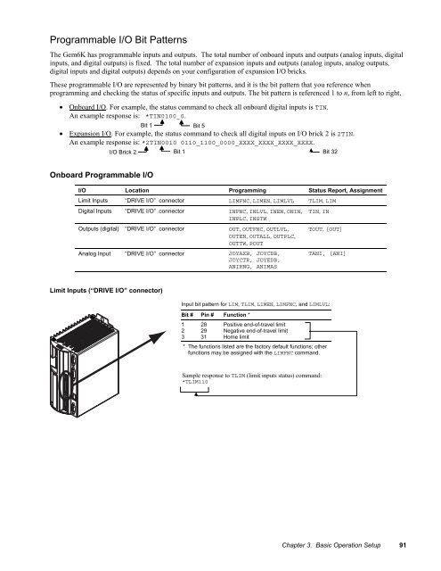
Limit Inputs (“DRIVE I/O” connector)<br />
Input bit pattern for LIM, TLIM, LIMEN, LIMFNC, <strong>and</strong> LIMLVL:<br />
Bit # Pin # Function *<br />
1 28 Positive end-of-travel limit<br />
2 29 Negative end-of-travel limit<br />
3 31 Home limit<br />
* The functions listed are the factory default functions; other<br />
functions may be assigned with the LIMFNC comm<strong>and</strong>.<br />
Sample response to TLIM (limit inputs status) comm<strong>and</strong>:<br />
*TLIM110<br />
Chapter 3. Basic Operation Setup 91


