

Gemini GV6K and Gemini GT6K Programmer's Guide
Gemini GV6K and Gemini GT6K Programmer's Guide
Gemini GV6K and Gemini GT6K Programmer's Guide

You also want an ePaper? Increase the reach of your titles
YUMPU automatically turns print PDFs into web optimized ePapers that Google loves.
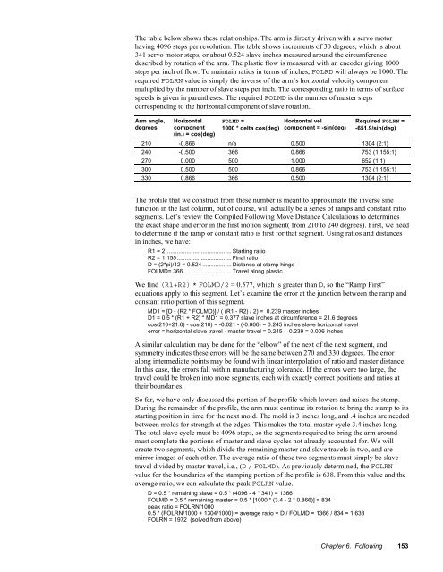
The table below shows these relationships. The arm is directly driven with a servo motor<br />
having 4096 steps per revolution. The table shows increments of 30 degrees, which is about<br />
341 servo motor steps, or about 0.524 slave inches measured around the circumference<br />
described by rotation of the arm. The plastic flow is measured with an encoder giving 1000<br />
steps per inch of flow. To maintain ratios in terms of inches, FOLRD will always be 1000. The<br />
required FOLRN value is simply the inverse of the arm’s horizontal velocity component<br />
multiplied by the number of slave steps per inch. The corresponding ratio in terms of surface<br />
speeds is given in parentheses. The required FOLMD is the number of master steps<br />
corresponding to the horizontal component of slave rotation.<br />
Arm angle,<br />
degrees<br />
Horizontal<br />
component<br />
(in.) = cos(deg)<br />
FOLMD =<br />
1000 * delta cos(deg)<br />
Horizontal vel<br />
component = -sin(deg)<br />
Required FOLRN =<br />
-651.9/sin(deg)<br />
210 -0.866 n/a 0.500 1304 (2:1)<br />
240 -0.500 366 0.866 753 (1.155:1)<br />
270 0.000 500 1.000 652 (1:1)<br />
300 0.500 500 0.866 753 (1.155:1)<br />
330 0.866 366 0.500 1304 (2:1)<br />
The profile that we construct from these number is meant to approximate the inverse sine<br />
function in the last column, but of course, will actually be a series of ramps <strong>and</strong> constant ratio<br />
segments. Let’s review the Compiled Following Move Distance Calculations to determines<br />
the exact shape <strong>and</strong> error in the first motion segment( from 210 to 240 degrees). First, we need<br />
to determine if the ramp or constant ratio is first for that segment. Using ratios <strong>and</strong> distances<br />
in inches, we have:<br />
R1 = 2......................................... Starting ratio<br />
R2 = 1.155.................................. Final ratio<br />
D = (2*pi)/12 = 0.524 .................. Distance at stamp hinge<br />
FOLMD=.366.............................. Travel along plastic<br />
We find (R1+R2) * FOLMD/2 = 0.577, which is greater than D, so the “Ramp First”<br />
equations apply to this segment. Let’s examine the error at the junction between the ramp <strong>and</strong><br />
constant ratio portion of this segment.<br />
MD1 = [D - (R2 * FOLMD)] / ( (R1 - R2) / 2) = 0.239 master inches<br />
D1 = 0.5 * (R1 + R2) * MD1 = 0.377 slave inches at circumference = 21.6 degrees<br />
cos(210+21.6) - cos(210) = -0.621 - (-0.866) = 0.245 inches slave horizontal travel<br />
error = horizontal slave travel - master travel = 0.245 - 0.239 = 0.006 inches<br />
A similar calculation may be done for the “elbow” of the next of the next segment, <strong>and</strong><br />
symmetry indicates these errors will be the same between 270 <strong>and</strong> 330 degrees. The error<br />
along intermediate points may be found with linear interpolation of ratio <strong>and</strong> master distance.<br />
In this case, the errors fall within manufacturing tolerance. If the errors were too large, the<br />
travel could be broken into more segments, each with exactly correct positions <strong>and</strong> ratios at<br />
their boundaries.<br />
So far, we have only discussed the portion of the profile which lowers <strong>and</strong> raises the stamp.<br />
During the remainder of the profile, the arm must continue its rotation to bring the stamp to its<br />
starting position in time for the next mold. The mold is 3 inches long, <strong>and</strong> .4 inches are needed<br />
between molds for strength at the edges. This makes the total master cycle 3.4 inches long.<br />
The total slave cycle must be 4096 steps, so the segments required to bring the arm around<br />
must complete the portions of master <strong>and</strong> slave cycles not already accounted for. We will<br />
create two segments, which divide the remaining master <strong>and</strong> slave travels in two, <strong>and</strong> are<br />
mirror images of each other. The average ratio of these two segments must simply be slave<br />
travel divided by master travel, i.e., (D / FOLMD). As previously determined, the FOLRN<br />
value for the boundaries of the stamping portion of the profile is 638. From this value <strong>and</strong> the<br />
average ratio, we can calculate the peak FOLRN value.<br />
D = 0.5 * remaining slave = 0.5 * (4096 - 4 * 341) = 1366<br />
FOLMD = 0.5 * remaining master = 0.5 * [1000 * (3.4 - 2 * 0.866)] = 834<br />
peak ratio = FOLRN/1000<br />
0.5 * (FOLRN/1000 + 1304/1000) = average ratio = D / FOLMD = 1366 / 834 = 1.638<br />
FOLRN = 1972 (solved from above)<br />
Chapter 6. Following 153


