

Gemini GV6K and Gemini GT6K Programmer's Guide
Gemini GV6K and Gemini GT6K Programmer's Guide
Gemini GV6K and Gemini GT6K Programmer's Guide

Create successful ePaper yourself
Turn your PDF publications into a flip-book with our unique Google optimized e-Paper software.
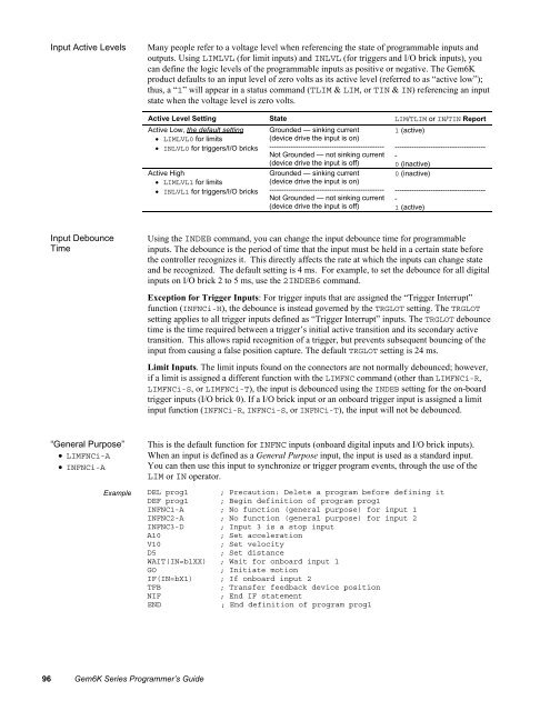
Input Active Levels<br />
Many people refer to a voltage level when referencing the state of programmable inputs <strong>and</strong><br />
outputs. Using LIMLVL (for limit inputs) <strong>and</strong> INLVL (for triggers <strong>and</strong> I/O brick inputs), you<br />
can define the logic levels of the programmable inputs as positive or negative. The Gem6K<br />
product defaults to an input level of zero volts as its active level (referred to as “active low”);<br />
thus, a “1” will appear in a status comm<strong>and</strong> (TLIM & LIM, or TIN & IN) referencing an input<br />
state when the voltage level is zero volts.<br />
Active Level Setting State LIM/TLIM or IN/TIN Report<br />
Active Low, the default setting<br />
• LIMLVL0 for limits<br />
• INLVL0 for triggers/I/O bricks<br />
Active High<br />
• LIMLVL1 for limits<br />
• INLVL1 for triggers/I/O bricks<br />
Grounded — sinking current<br />
(device drive the input is on)<br />
------------------------------------------------<br />
Not Grounded — not sinking current<br />
(device drive the input is off)<br />
Grounded — sinking current<br />
(device drive the input is on)<br />
------------------------------------------------<br />
Not Grounded — not sinking current<br />
(device drive the input is off)<br />
1 (active)<br />
--------------------------------------<br />
-<br />
0 (inactive)<br />
0 (inactive)<br />
--------------------------------------<br />
-<br />
1 (active)<br />
Input Debounce<br />
Time<br />
Using the INDEB comm<strong>and</strong>, you can change the input debounce time for programmable<br />
inputs. The debounce is the period of time that the input must be held in a certain state before<br />
the controller recognizes it. This directly affects the rate at which the inputs can change state<br />
<strong>and</strong> be recognized. The default setting is 4 ms. For example, to set the debounce for all digital<br />
inputs on I/O brick 2 to 5 ms, use the 2INDEB6 comm<strong>and</strong>.<br />
Exception for Trigger Inputs: For trigger inputs that are assigned the “Trigger Interrupt”<br />
function (INFNCi-H), the debounce is instead governed by the TRGLOT setting. The TRGLOT<br />
setting applies to all trigger inputs defined as “Trigger Interrupt” inputs. The TRGLOT debounce<br />
time is the time required between a trigger’s initial active transition <strong>and</strong> its secondary active<br />
transition. This allows rapid recognition of a trigger, but prevents subsequent bouncing of the<br />
input from causing a false position capture. The default TRGLOT setting is 24 ms.<br />
Limit Inputs. The limit inputs found on the connectors are not normally debounced; however,<br />
if a limit is assigned a different function with the LIMFNC comm<strong>and</strong> (other than LIMFNCi-R,<br />
LIMFNCi-S, or LIMFNCi-T), the input is debounced using the INDEB setting for the on-board<br />
trigger inputs (I/O brick 0). If a I/O brick input or an onboard trigger input is assigned a limit<br />
input function (INFNCi-R, INFNCi-S, or INFNCi-T), the input will not be debounced.<br />
“General Purpose”<br />
• LIMFNCi-A<br />
• INFNCi-A<br />
This is the default function for INFNC inputs (onboard digital inputs <strong>and</strong> I/O brick inputs).<br />
When an input is defined as a General Purpose input, the input is used as a st<strong>and</strong>ard input.<br />
You can then use this input to synchronize or trigger program events, through the use of the<br />
LIM or IN operator.<br />
Example DEL prog1 ; Precaution: Delete a program before defining it<br />
DEF prog1 ; Begin definition of program prog1<br />
INFNC1-A ; No function (general purpose) for input 1<br />
INFNC2-A ; No function (general purpose) for input 2<br />
INFNC3-D ; Input 3 is a stop input<br />
A10<br />
; Set acceleration<br />
V10<br />
; Set velocity<br />
D5<br />
; Set distance<br />
WAIT(IN=b1XX) ; Wait for onboard input 1<br />
GO<br />
; Initiate motion<br />
IF(IN=bX1) ; If onboard input 2<br />
TFB<br />
; Transfer feedback device position<br />
NIF<br />
; End IF statement<br />
END<br />
; End definition of program prog1<br />
96 Gem6K Series Programmer’s <strong>Guide</strong>


