

Apalis Carrier Board Design Guide - Toradex
Apalis Carrier Board Design Guide - Toradex
Apalis Carrier Board Design Guide - Toradex
- No tags were found...

You also want an ePaper? Increase the reach of your titles
YUMPU automatically turns print PDFs into web optimized ePapers that Google loves.
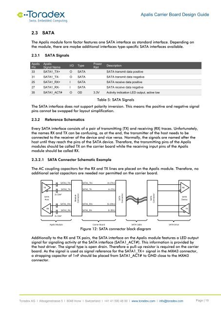
<strong>Apalis</strong> <strong>Carrier</strong> <strong>Board</strong> <strong>Design</strong> <strong>Guide</strong>2.3 SATAThe <strong>Apalis</strong> module form factor features one SATA interface as standard interface. Depending onthe module, there are maybe additional interfaces type-specific SATA interfaces available.2.3.1 SATA Signals<strong>Apalis</strong>Pin<strong>Apalis</strong>Signal NameI/OTypePowerRailDescription33 SATA1_TX+ O SATA SATA transmit data positive31 SATA1_TX- O SATA SATA transmit data negative25 SATA1_RX+ I SATA SATA receive data positive27 SATA1_RX- I SATA SATA receive data negative35 SATA1_ACT# O OD 3.3V Activity indication LED output, active lowTable 5: SATA SignalsThe SATA interface does not support polarity inversion. This means the positive and negative signalpins cannot be swapped for layout simplification.2.3.2 Reference SchematicsEvery SATA interface consists of a pair of transmitting (TX) and receiving (RX) traces. Unfortunately,the names RX and TX can be confusing, as at the end, the transmitter of the host needs to beconnected to the receiver of the device and vice versa. Normally, the signals are named after thehost until they reach the pins of the SATA device. Therefore, the transmitting pins of the <strong>Apalis</strong>modules should be called TX on the carrier board while the receiving input pins of the <strong>Apalis</strong>module should be called RX.2.3.2.1 SATA Connector Schematic ExampleThe AC coupling capacitors for the RX and TX lines are placed on the <strong>Apalis</strong> module. Therefore, noadditional serial capacitors are needed nor permitted on the carrier board.SATA1_TX+SATA1_TX+A+ (TX+)TXSATA1_TX-SATA1_TX-A- (TX-)RXSATAHost2x 10nFSATA1_RX+ModuleConnectorSATA1_RX+B+ (RX+)SATAConnectorSATAConnectorSATADeviceRXSATA1_RX-SATA1_RX-B- (RX-)TX2x 10nF<strong>Apalis</strong> Module <strong>Carrier</strong> <strong>Board</strong> SATA CableSATA DriveFigure 12: SATA connector block diagramAdditionally to the RX and TX pairs, the SATA interface on the <strong>Apalis</strong> module features a LED outputsignal for signaling activity at the SATA interface (SATA1_ACT#). This information is provided bythe host driver. The signal type is open drain. Therefore a pull-up resistor is required on the carrierboard. As the signal is used as signal reference for the SATA1_TX+ signal in the MXM3 connector,a strapping capacitor of 1nF should be placed from SATA1_ACT# to GND close to the MXM3connector.<strong>Toradex</strong> AG l Altsagenstrasse 5 l 6048 Horw l Switzerland l +41 41 500 48 00 l www.toradex.com l info@toradex.com Page | 19


