

Apalis Carrier Board Design Guide - Toradex
Apalis Carrier Board Design Guide - Toradex
Apalis Carrier Board Design Guide - Toradex
- No tags were found...

Create successful ePaper yourself
Turn your PDF publications into a flip-book with our unique Google optimized e-Paper software.
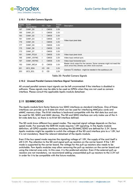
<strong>Apalis</strong> <strong>Carrier</strong> <strong>Board</strong> <strong>Design</strong> <strong>Guide</strong>2.10.1 Parallel Camera Signals<strong>Apalis</strong>Pin<strong>Apalis</strong>Signal NameI/OTypePowerRail187 CAM1_D0 I CMOS 3.3V185 CAM1_D1 I CMOS 3.3V183 CAM1_D2 I CMOS 3.3V181 CAM1_D3 I CMOS 3.3V179 CAM1_D4 I CMOS 3.3V177 CAM1_D5 I CMOS 3.3V175 CAM1_D6 I CMOS 3.3V173 CAM1_D7 I CMOS 3.3VDescriptionVideo input pixel data191 CAM1_PCLK I CMOS 3.3V Video input pixel clock195 CAM1_VSYNC I CMOS 3.3V Video input vertical sync197 CAM1_HSYNC I CMOS 3.3V Video input horizontal sync193 CAM1_MCLK O CMOS 3.3V201 I2C3_SDA I/O OD 3.3V203 I2C3_SCL O OD 3.3VMaster clock output for the camera. Some cameras might not need thisclock since they already use other clock sourcesCamera I 2 C interface - might be needed in the autofocus unitTable 20: Parallel Camera Signals2.10.2 Unused Parallel Camera Interface Signal TerminationAll unused parallel camera input signals can be left unconnected if the interface is disabled insoftware. These signals may be able to be used as GPIOs when they are not used as camerainterface. Please consult the applicable <strong>Apalis</strong> module datasheet.2.11 SD/MMC/SDIOThe <strong>Apalis</strong> module form factor features two SDIO interfaces as standard interfaces. One of theseinterfaces can provide up to 8 data bit which can be used for interfacing MMCplus cards andeMMC memory chips. The 8-bit interface is backward compatible with the 4bit data bus and canbe used for SD, SDIO and MMC devices. The SD and SDIO interface can only make use of the 4-bit wide data bus, as there is no 8-bit SD interface defined.The SD cards know different bus speed modes. The required signal voltage depends on the busspeed mode. For example the SDR104 mode requires 1.8V signaling. In the <strong>Apalis</strong> moduledefinition, all GPIO capable interfaces including the SD/MMC/SDIO are defined for 3.3V. Some<strong>Apalis</strong> modules might be capable to switch the voltages of the SD card interface pins to a 1.8V, butit is not mandatory. Read the relevant datasheet of the <strong>Apalis</strong> module.Even if the bus speed mode requires the signaling voltage of 1.8V, the supply of the card itself isstill 3.3V. Pay attention to the SD card signal pull-up resistors on the carrier board. If the 1.8Vmode is supported by the carrier board, the voltage for the pull-up resistors also needs to beswitchable. Few <strong>Apalis</strong> modules may allow removing the pull-up resistors on the carrier board andusing the internal ones only. In this case, it is the preferred solution. Even if the external pull-upresistors are not mandatory, we recommend adding unassembled pull-up resistors to the 3.3V railin order for it to be compatible with the future modules.<strong>Toradex</strong> AG l Altsagenstrasse 5 l 6048 Horw l Switzerland l +41 41 500 48 00 l www.toradex.com l info@toradex.com Page | 46


