

Apalis Carrier Board Design Guide - Toradex
Apalis Carrier Board Design Guide - Toradex
Apalis Carrier Board Design Guide - Toradex
- No tags were found...

Create successful ePaper yourself
Turn your PDF publications into a flip-book with our unique Google optimized e-Paper software.
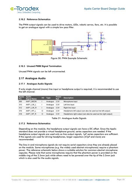
<strong>Apalis</strong> <strong>Carrier</strong> <strong>Board</strong> <strong>Design</strong> <strong>Guide</strong>2.16.2 Reference SchematicsThe PWM output signals can be used to drive motors, LEDs, robotic servos, fans, etc. It is possibleto get an analogue signal with a simple low pass filter.X1E<strong>Apalis</strong> - PWM and AnalogMM70-314-310B15 of 25AN1_ADC0AN1_ADC1AN1_ADC2AN1_TSWIP_ADC3PWM1PWM2PWM3PWM43053073093112468R92R9310K10K330nFC118330nF16VGNDC11916VGNDPWM3PWM4GNDX17321826936-3PWM1PWM2GNDR116100KAnalogue OutputFigure 50: PWM Example Schematic23.3V_SW1 6GNDR113120RLED1GREENT5ASI-1024-XGND5R117100K3.3V_SW4 3GNDR114120RLED2GREENT5BSI-1024-X2.16.3 Unused PWM Signal TerminationUnused PWM signals can be left unconnected.2.17 Analogue Audio2.17.1 Analogue Audio SignalsIf only single channel (mono) line input or headphone output is required, it is recommended to usethe left channel.<strong>Apalis</strong>Pin<strong>Apalis</strong>Signal NameI/OTypePowerRailDescription306 AAP1_MICIN I Analogue 3.3V Microphone input310 AAP1_LIN_L I Analogue 3.3V Left line input312 AAP1_LIN_R I Analogue 3.3V Right line input316 AAP1_HP_L O Analogue 3.3V Headphone left output (can also be used as line left output)318 AAP1_HP_R O Analogue 3.3V Headphone right output (can also be used as line right output)2.17.2 Reference SchematicsTable 31: Analogue Audio SignalsDepending on the module, the headphone output signals can have a DC offset. Since the <strong>Apalis</strong>standard does not provide a virtual headphone ground, series capacitors are needed. If theheadphone output signals are used only as line output signals, 1µF series capacitors are sufficient.If the signals are used for driving headphones, larger capacitors (47µF and more) arerecommended.The line-in and microphone signals do not require serial capacitors since they are already placedon the module. Some microphones (e.g. the widely used electret microphones) require a phantompower. The reference schematic below shows a suitable solution for common electret microphonecapsules. Please note that some microphones require that the phantom power is provided on themiddle ring of the 3.5mm jack while others need to be powered over the tip of the 3.5mm jackwhich is also used for the audio signals.<strong>Toradex</strong> AG l Altsagenstrasse 5 l 6048 Horw l Switzerland l +41 41 500 48 00 l www.toradex.com l info@toradex.com Page | 55


