

Apalis Carrier Board Design Guide - Toradex
Apalis Carrier Board Design Guide - Toradex
Apalis Carrier Board Design Guide - Toradex
- No tags were found...

Create successful ePaper yourself
Turn your PDF publications into a flip-book with our unique Google optimized e-Paper software.
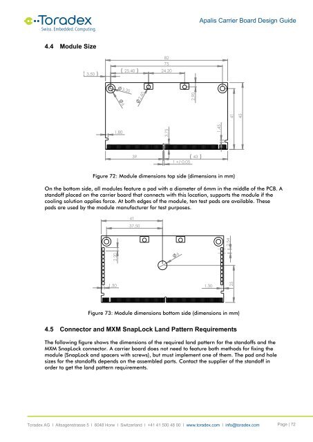
<strong>Apalis</strong> <strong>Carrier</strong> <strong>Board</strong> <strong>Design</strong> <strong>Guide</strong>4.4 Module Size3.5025.40827524.203.202.60641453.751.452.901.801 +/-0.05Figure 72: Module dimensions top side (dimensions in mm)On the bottom side, all modules feature a pad with a diameter of 6mm in the middle of the PCB. Astandoff placed on the carrier board that connects with this location, supports the module if thecooling solution applies force. At both edges of the module, ten test pads are available. Thesepads are used by the module manufacturer for test purposes.4137.5062.202.541.3025Figure 73: Module dimensions bottom side (dimensions in mm)4.5 Connector and MXM SnapLock Land Pattern RequirementsThe following figure shows the dimensions of the required land pattern for the standoffs and theMXM SnapLock connector. A carrier board does not need to feature both methods for fixing themodule (SnapLock and spacers with screws), but must implement one of them. The pad and holesizes for the standoffs depends on the assembled parts. Contact the supplier of the standoff inorder to get the land pattern requirements.<strong>Toradex</strong> AG l Altsagenstrasse 5 l 6048 Horw l Switzerland l +41 41 500 48 00 l www.toradex.com l info@toradex.com Page | 72


