

Apalis Carrier Board Design Guide - Toradex
Apalis Carrier Board Design Guide - Toradex
Apalis Carrier Board Design Guide - Toradex
- No tags were found...

Create successful ePaper yourself
Turn your PDF publications into a flip-book with our unique Google optimized e-Paper software.
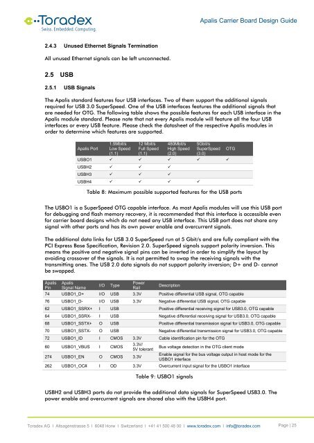
<strong>Apalis</strong> <strong>Carrier</strong> <strong>Board</strong> <strong>Design</strong> <strong>Guide</strong>2.4.3 Unused Ethernet Signals TerminationAll unused Ethernet signals can be left unconnected.2.5 USB2.5.1 USB SignalsThe <strong>Apalis</strong> standard features four USB interfaces. Two of them support the additional signalsrequired for USB 3.0 SuperSpeed. One of the USB interfaces features the additional signals thatare needed for OTG. The following table shows the possible features for each USB interface in the<strong>Apalis</strong> module standard. Please note that not every <strong>Apalis</strong> module will feature all the four USBinterfaces or every USB feature. Please check the datasheet of the respective <strong>Apalis</strong> modules inorder to determine which features are supported.<strong>Apalis</strong> Port1.5Mbit/sLow Speed(1.1)12 Mbit/sFull Speed(1.1)480Mbit/sHigh Speed(2.0)5Gbit/sSuperSpeed(3.0)USBO1 USBH2 USBH3 USBH4 OTGTable 8: Maximum possible supported features for the USB portsThe USBO1 is a SuperSpeed OTG capable interface. As most <strong>Apalis</strong> modules will use this USB portfor debugging and flash memory recovery, it is recommended that this interface is accessible evenfor carrier board designs which do not need any USB interface. This USB port does not share anysignal with other ports and has its own power enable and overcurrent signals.The additional data links for USB 3.0 SuperSpeed run at 5 Gbit/s and are fully compliant with thePCI Express Base Specification, Revision 2.0. SuperSpeed signals support polarity inversion. Thismeans the positive and negative signal pins can be inverted in order to simplify the layout byavoiding crossover of the signals. It is not permitted to swap the receiving signals with thetransmitting ones. The USB 2.0 data signals do not support polarity inversion; D+ and D- cannotbe swapped.<strong>Apalis</strong>Pin<strong>Apalis</strong>Signal NameI/OTypePowerRailDescription74 USBO1_D+ I/O USB 3.3V Positive differential USB signal, OTG capable76 USBO1_D- I/O USB 3.3V Negative differential USB signal, OTG capable62 USBO1_SSRX+ I USB Positive differential receiving signal for USB3.0, OTG capable64 USBO1_SSRX- I USB Negative differential receiving signal for USB3.0, OTG capable68 USBO1_SSTX+ O USB Positive differential transmission signal for USB3.0, OTG capable70 USBO1_SSTX- O USB Negative differential transmission signal for USB3.0, OTG capable72 USBO1_ID I CMOS 3.3V Cable identification pin for the OTG60 USBO1_VBUS I CMOS274 USBO1_EN O CMOS 3.3V3.3V/5V tolerantBus voltage detection in the OTG client modeEnable signal for the bus voltage output in host mode for theUSBO1 interface262 USBO1_OC# I OD 3.3V Overcurrent input signal for the USBO1 interfaceTable 9: USBO1 signalsUSBH2 and USBH3 ports do not provide the additional data signals for SuperSpeed USB3.0. Thepower enable and overcurrent signals are shared also with the USBH4 port.<strong>Toradex</strong> AG l Altsagenstrasse 5 l 6048 Horw l Switzerland l +41 41 500 48 00 l www.toradex.com l info@toradex.com Page | 25


