

Apalis Carrier Board Design Guide - Toradex
Apalis Carrier Board Design Guide - Toradex
Apalis Carrier Board Design Guide - Toradex
- No tags were found...

Create successful ePaper yourself
Turn your PDF publications into a flip-book with our unique Google optimized e-Paper software.
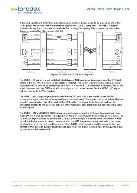
<strong>Apalis</strong> <strong>Carrier</strong> <strong>Board</strong> <strong>Design</strong> <strong>Guide</strong>If the USB signals are externally available, ESD protection diodes need to be placed on all of theUSB signals. Make sure that the protection diodes are USB 3.0 compliant. The USB 2.0 signalsadditionally require a common mode choke for passing EMI testing. Use common mode chokesthat are specified for High-speed USB 2.0.RX/TXUSB 2.0/1.1USBO1_D+USBO1_D+USBO1_D-USBO1_D-TVSDiodeD+D-RX/TXUSB 2.0/1.1USB 3.0 OTG ControllerTXSuperSpeedRXModuleConnectorTVSDiodeTVSDiodeUSBO1_SSTX+USBO1_SSTX-2x 100nFUSBO1_SSRX+USBO1_SSRX-USBO1_SSTX+USBO1_SSTX-USBO1_SSRX+USBO1_SSRX-SSTX+SSTX-SSRX+SSRX-USB 3.0 OTG ConnectorUSB 3.0 ConnectorRXSuperSpeedTXUSB 3.0 Device2x 100nF<strong>Apalis</strong> Module<strong>Carrier</strong> <strong>Board</strong>USB CableFigure 20: USB 3.0 OTG Block DiagramUSB DriveThe USBO1_ID signal is used to detect which type of USB connector is plugged into the OTG jack(Micro-AB jack). When a Micro-A connector is inserted, the ID pin is connected to signal ground,causing the OTG port to be configured as a host. If a Micro-B USB connector is inserted, the ID pinis left unbiased and the OTG port will be configured as a slave device. For the USBO1_ID signal apull-up resistor to 3.3V is needed.The USBO1_VBUS input signal is only used if the OTG port is in client mode (Micro-B USBconnector plugged in or by software configured as slave only). The signal is used to detect whethera host is connected on the other end of the USB cable. This signal is 5V tolerant and can beconnected directly to the power supply pin of the USB jack. ESD protection diodes should be usedfor this signal.The USBO1_EN and USBO1_OC# signals are only used when the OTG port is operating in hostmode (Micro-A USB connector is plugged in or the port is configured by software as host only). TheUSBO1_EN signal is used to enable the USB bus power supply if it needs to be switchable. A USBcompliant design needs to detect overcurrent on the USB bus power supply and switch the poweroff should an over-current condition occur. The USBO1_OC# signal is used to signal to the hostcontroller that an over-current condition has occurred. This signal is active-low and requires a pullupresistor on the baseboard.<strong>Toradex</strong> AG l Altsagenstrasse 5 l 6048 Horw l Switzerland l +41 41 500 48 00 l www.toradex.com l info@toradex.com Page | 27


