

Apalis Carrier Board Design Guide - Toradex
Apalis Carrier Board Design Guide - Toradex
Apalis Carrier Board Design Guide - Toradex
- No tags were found...

You also want an ePaper? Increase the reach of your titles
YUMPU automatically turns print PDFs into web optimized ePapers that Google loves.
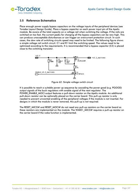
<strong>Apalis</strong> <strong>Carrier</strong> <strong>Board</strong> <strong>Design</strong> <strong>Guide</strong>3.5 Reference SchematicsPlace enough power supply bypass capacitors on the voltage inputs of the peripheral devices (see<strong>Toradex</strong> Layout <strong>Design</strong> <strong>Guide</strong>). Place a bypass capacitor on each power input pin of the <strong>Apalis</strong>module. Be aware of the total capacity on a voltage rail when switching the voltage. If the rails areswitched on too fast, the current peaks for charging all the bypass capacitors can be very high. Thiscan produce unacceptable disturbances or can trigger an overcurrent protection circuit. In suchcases, the slew rate of switching circuits speed may need to be limited. The following figure showsa simple voltage rail switch circuit. C1 and R1 limit the switching speed. The values need to beoptimized according to the requirements. It is recommended that a bypass capacitor (C2) is placedclose to the switching transistor.+V3.3R2 100KENABLE_V3.3_SWITCHEDGNDC2100nF16VC110nF16V26T2SI1016CX1Figure 62: Simple voltage switch circuitIt is possible to reach a suitable power up sequence by cascading the power good (e.g. PGOOD)output signals of the buck regulators with enable signal of the next regulator. ThePOWER_ENABLE_MOCI output features a pull-down resistor on the <strong>Apalis</strong> module. An additionalpull-down resistor can be optionally placed on the carrier board. This pull-up resistor is onlyneeded to prevent unwanted enabling of the peripheral voltages if the module is not inserted. Fordesigns in which the module is never removed, this pull-up is not required.The RESET_MICO# and RESET_MOCI# do not need any pull-up resistors on the carrier board asthese resistors are implemented on the module. The WAKE1_MICO# requires a pull-up resistor onthe carrier board if the wake function is implemented.21GND3T1 IRLML6401R1 47K+V3.3_SWITCHED<strong>Toradex</strong> AG l Altsagenstrasse 5 l 6048 Horw l Switzerland l +41 41 500 48 00 l www.toradex.com l info@toradex.com Page | 67


