

Apalis Carrier Board Design Guide - Toradex
Apalis Carrier Board Design Guide - Toradex
Apalis Carrier Board Design Guide - Toradex
- No tags were found...

Create successful ePaper yourself
Turn your PDF publications into a flip-book with our unique Google optimized e-Paper software.
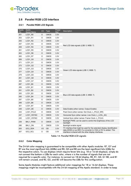
<strong>Apalis</strong> <strong>Carrier</strong> <strong>Board</strong> <strong>Design</strong> <strong>Guide</strong>2.6 Parallel RGB LCD Interface2.6.1 Parallel RGB LCD Signals<strong>Apalis</strong>Pin<strong>Apalis</strong>Signal NameI/OTypePowerRail251 LCD1_R0 O CMOS 3.3V253 LCD1_R1 O CMOS 3.3V255 LCD1_R2 O CMOS 3.3V257 LCD1_R3 O CMOS 3.3V259 LCD1_R4 O CMOS 3.3V261 LCD1_R5 O CMOS 3.3V263 LCD1_R6 O CMOS 3.3V265 LCD1_R7 O CMOS 3.3V269 LCD1_G0 O CMOS 3.3V271 LCD1_G1 O CMOS 3.3V273 LCD1_G2 O CMOS 3.3V275 LCD1_G3 O CMOS 3.3V277 LCD1_G4 O CMOS 3.3V279 LCD1_G5 O CMOS 3.3V281 LCD1_G6 O CMOS 3.3V283 LCD1_G7 O CMOS 3.3V287 LCD1_B0 O CMOS 3.3V289 LCD1_B1 O CMOS 3.3V291 LCD1_B2 O CMOS 3.3V293 LCD1_B3 O CMOS 3.3V295 LCD1_B4 O CMOS 3.3V297 LCD1_B5 O CMOS 3.3V299 LCD1_B6 O CMOS 3.3V301 LCD1_B7 O CMOS 3.3VDescriptionRed LCD data signals (LSB: 0, MSB: 7)Green LCD data signals (LSB: 0, MSB: 7)Blue LCD data signals (LSB: 0, MSB: 7)249 LCD1_DE O CMOS 3.3V Data Enable (other names: Output Enable)243 LCD1_PCLK O CMOS 3.3V Pixel Clock (other names: Dot Clock, L_PCLK_WR)247 LCD1_HSYNC O CMOS 3.3V Horizontal Sync (other names: Line Clock, L_LCKL_A0)245 LCD1_VSYNC O CMOS 3.3V Vertical Sync (other names: Frame Clock, L_FCLK)239 BKL1_PWM O CMOS 3.3V286 BKL1_ON O CMOS 3.3V Backlight enable signalBacklight PWM, can be used to control the brightness of the LCDbacklight205 I2C2_SDA I/O OD 3.3V I 2 C interface that might be used for the extended display identificationdata (EDID) or as DDC if a converter to VGA or DVI is added. This207 I2C2_SCL O OD 3.3V interface is shared with the other display interfaces.2.6.2 Color MappingTable 14: Parallel RGB LCD signalsThe 24-bit color mapping is guaranteed to be compatible with other <strong>Apalis</strong> modules. R7, G7 andB7 are the most significant bits (MSBs) and R0, G0 and B0 are the least significant bits (LSBs) forthe respective colors. To use displays which require fewer bits (e.g. 18 or 16-bit displays), simply donot connect the bottom n LSBs for each color, where n is the number of signals that are notrequired for a specific color. For instance, to connect an 18-bit display, R0, R1, G0, G1 B0, and B1will remain unused, and R2, G2, and B2 will become the LSBs for this configuration.Some <strong>Apalis</strong> Modules might feature additional color mappings for 18 or 16-bit displays. Thesemappings might be incompatible with the 24-bit mapping of the <strong>Apalis</strong> standard. In order to keep<strong>Toradex</strong> AG l Altsagenstrasse 5 l 6048 Horw l Switzerland l +41 41 500 48 00 l www.toradex.com l info@toradex.com Page | 33


