

Apalis Carrier Board Design Guide - Toradex
Apalis Carrier Board Design Guide - Toradex
Apalis Carrier Board Design Guide - Toradex
- No tags were found...

Create successful ePaper yourself
Turn your PDF publications into a flip-book with our unique Google optimized e-Paper software.
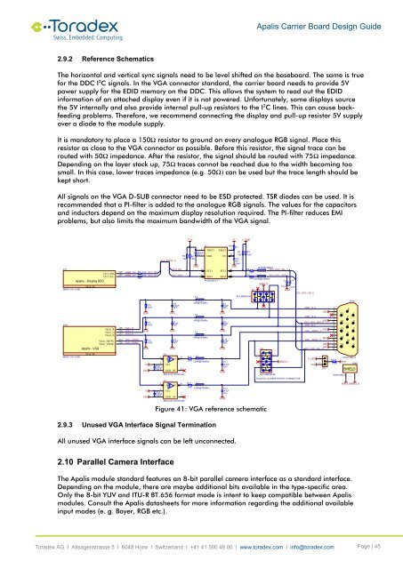
<strong>Apalis</strong> <strong>Carrier</strong> <strong>Board</strong> <strong>Design</strong> <strong>Guide</strong>2.9.2 Reference SchematicsThe horizontal and vertical sync signals need to be level shifted on the baseboard. The same is truefor the DDC I 2 C signals. In the VGA connector standard, the carrier board needs to provide 5Vpower supply for the EDID memory on the DDC. This allows the system to read out the EDIDinformation of an attached display even if it is not powered. Unfortunately, some displays sourcethe 5V internally and also provide internal pull-up resistors to the I 2 C lines. This can cause backfeedingproblems. Therefore, we recommend connecting the display and pull-up resistor 5V supplyover a diode to the module supply.It is mandatory to place a 150Ω resistor to ground on every analogue RGB signal. Place thisresistor as close to the VGA connector as possible. Before this resistor, the signal trace can berouted with 50Ω impedance. After the resistor, the signal should be routed with 75Ω impedance.Depending on the layer stack up, 75Ω traces cannot be reached due to the width becoming toosmall. In this case, lower traces impedance (e.g. 50Ω) can be used but the trace length should bekept short.All signals on the VGA D-SUB connector need to be ESD protected. TSR diodes can be used. It isrecommended that a PI-filter is added to the analogue RGB signals. The values for the capacitorsand inductors depend on the maximum display resolution required. The PI-filter reduces EMIproblems, but also limits the maximum bandwidth of the VGA signal.3.3V5VV_DISPX1YI2C2_SDAI2C2_SCL<strong>Apalis</strong> - Display DDC25 of 25MM70-314-310B1X1WVGA1_RVGA1_GVGA1_BVGA1_HSYNCVGA1_VSYNC<strong>Apalis</strong> - VGA205207208210212214216MXM3_205MXM3_207VGA1_RVGA1_GVGA1_BVGA1_HSYNCVGA1_VSYNCR7R922R22RGNDGNDGNDI2C2_SDAI2C2_SCLR10150RR11150RR12150RI2C2_DDC[0..1]I2C2_SCLI2C2_SDAGNDGNDGNDC510pF50VC710pF50VC910pF50VR41.8KR51.8KGND2C1100nF16V 1L3600mA40R@100MHzL4600mA40R@100MHzL534IC1600mA40R@100MHzVREF1GNDSCL1SDA1PCA9306DCTTVREF2ENSCL2SDA2GNDGNDGNDC610pF50VC810pF50VC1010pF50V100K78C216V100nFGND65R1R21.8KR31.8KR6R822R22RRCLAMP0504SD1L1220R@100MHzI2C2_DDC_SCL_C500mAL2I2C2_DDC_SDA_C500mA220R@100MHzC3SHIELDD2C44.7pF 4.7pFGNDI2C2_DDC_C[0..1]VGA1_R_CVGA1_G_CVGA1_B_CGNDGNDI2C2_DDC_SDA_CVGA1_HSYNC_CVGA1_VSYNC_CGNDPIN9GNDGNDI2C2_DDC_SCL_C1611271238134914510151112131415X24A61728394105MM70-314-310B123 of 255VGND5VGNDIC2L624 R13A Y500mA33R 220R@100MHzC11SHIELD547pFC12 VCC100nF50V16V31GND NCGNDSN74LVC1G17DCKRRCLAMP0504SPLACE D1, D2 NEAR THE DVI-I CONNECTORIC3L724 R15A Y500mA33R 220R@100MHzC135VCC47pFC14100nF50V16V31GND NCGNDSN74LVC1G17DCKRFigure 41: VGA reference schematic3V_DISP1GNDJP1HDR15SN-H2 R14PIN9120RX24BSHIELDHDR15SN-HSHIELD SHIELD2.9.3 Unused VGA Interface Signal TerminationAll unused VGA interface signals can be left unconnected.2.10 Parallel Camera InterfaceThe <strong>Apalis</strong> module standard features an 8-bit parallel camera interface as a standard interface.Depending on the module, there are maybe additional bits available in the type-specific area.Only the 8-bit YUV and ITU-R BT.656 format mode is intent to keep compatible between <strong>Apalis</strong>modules. Consult the <strong>Apalis</strong> datasheets for more information regarding the additional availableinput modes (e. g. Bayer, RGB etc.).<strong>Toradex</strong> AG l Altsagenstrasse 5 l 6048 Horw l Switzerland l +41 41 500 48 00 l www.toradex.com l info@toradex.com Page | 45


