

Apalis Carrier Board Design Guide - Toradex
Apalis Carrier Board Design Guide - Toradex
Apalis Carrier Board Design Guide - Toradex
- No tags were found...

You also want an ePaper? Increase the reach of your titles
YUMPU automatically turns print PDFs into web optimized ePapers that Google loves.
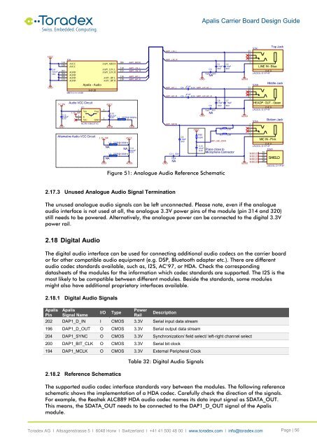
<strong>Apalis</strong> <strong>Carrier</strong> <strong>Board</strong> <strong>Design</strong> <strong>Guide</strong>AVCCGNDC41100nF16VX1H314AVCC320AVCC3033043083135V_SWGNDC132.2uF6.3VAGNDAGNDAGNDAGNDMM70-314-310B1IC11Vin3.3V_SW3E4N/C<strong>Apalis</strong> - Audio8 of 25Audio VCC CircuitVoutGNDNCP511SN33T1GAlternative Audio VCC CircuitAAP1_MICINAAP1_LIN_LAAP1_LIN_RAAP1_HP_LAAP1_HP_R523.3V_SWGNDAVCCAGNDNANAC122.2uF6.3VL2L3L1306310312316318220R@100MHz2AAAP1_MICINAAP1_LIN_LAAP1_LIN_RAAP1_HP_LAAP1_HP_R220R@100MHz2ANA220R@100MHz2AGNDAVCCAGNDC142.2uF6.3VGNDAAP1_LIN_LAAP1_LIN_RAAP1_HP_LAAP1_HP_RAAP1_MICIN15pFNA47uF 6.3V +C447uFC5 + 6.3V15pF 50VNAGNDFigure 51: Analogue Audio Reference SchematicC1150VC915pF50V+C3AAP1_HP_AC_LAAP1_HP_AC_RC815pF 50VNAGNDR88100RC115pF50VC615pF50VC215pF50VC715pF50VAVCC R8 2.2KR3 2.2KAAP1_MIC_PWRC1047uFPlace close to6.3VMicrophone ConnectorTop JackX26C323334351LINE IN - BlueSHIELDSHIELDSHIELDSHIELDAGND3 of 3JA3333L-D11P-4FAGNDMiddle JackX26B222324251HEADP. OUT - Green2 of 3JA3333L-D11P-4FAGNDBottom JackX26A23451MIC IN - Pink2 of 3JA3333L-D11P-4FX26DS1S2S3S4SHIELDJA3333L-D11P-4F2.17.3 Unused Analogue Audio Signal TerminationThe unused analogue audio signals can be left unconnected. Please note, even if the analogueaudio interface is not used at all, the analogue 3.3V power pins of the module (pin 314 and 320)still needs to be powered. Alternatively, the analogue power can be connected to the digital 3.3Vpower rail.2.18 Digital AudioThe digital audio interface can be used for connecting additional audio codecs on the carrier boardor for other compatible audio equipment (e.g. DSP, Bluetooth adapter etc.). There are differentaudio codec standards available, such as, I2S, AC’97, or HDA. Check the correspondingdatasheets of the modules for the information which codec standards are supported. The I2S is themost likely to be compatible between different modules. Beside the standards, some modulesmight also have additional proprietary interfaces available.2.18.1 Digital Audio Signals<strong>Apalis</strong>Pin<strong>Apalis</strong>Signal NameI/OTypePowerRailDescription202 DAP1_D_IN I CMOS 3.3V Serial input data stream196 DAP1_D_OUT O CMOS 3.3V Serial output data stream204 DAP1_SYNC O CMOS 3.3V Synchronization/ field select/ left-right channel select200 DAP1_BIT_CLK O CMOS 3.3V Serial bit clock194 DAP1_MCLK O CMOS 3.3V External Peripheral Clock2.18.2 Reference SchematicsTable 32: Digital Audio SignalsThe supported audio codec interface standards vary between the modules. The following referenceschematic shows the implementation of a HDA codec. Carefully check the direction of the signals.For example, the Realtek ALC889 HDA audio codec names its data input signal as SDATA_OUT.This means, the SDATA_OUT needs to be connected to the DAP1_D_OUT signal of the <strong>Apalis</strong>module.<strong>Toradex</strong> AG l Altsagenstrasse 5 l 6048 Horw l Switzerland l +41 41 500 48 00 l www.toradex.com l info@toradex.com Page | 56


