

Apalis Carrier Board Design Guide - Toradex
Apalis Carrier Board Design Guide - Toradex
Apalis Carrier Board Design Guide - Toradex
- No tags were found...

You also want an ePaper? Increase the reach of your titles
YUMPU automatically turns print PDFs into web optimized ePapers that Google loves.
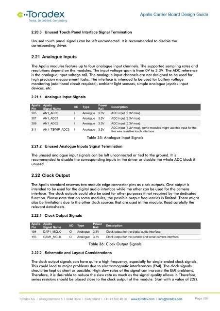
<strong>Apalis</strong> <strong>Carrier</strong> <strong>Board</strong> <strong>Design</strong> <strong>Guide</strong>2.20.3 Unused Touch Panel Interface Signal TerminationUnused touch panel signals can be left unconnected. It is recommended to disable thecorresponding driver.2.21 Analogue InputsThe <strong>Apalis</strong> modules feature up to four analogue input channels. The supported sampling rates andresolutions depend on the modules. The input voltage span is from 0V to 3.3V. The ADC referenceis the analogue input voltage rail. The analogue input channels are not designed to be used forhigh precision measurement tasks. The interface is intended to be used for battery voltagemonitoring (additional circuit required), ambient light sensors, simple analogue joystick inputdevices, etc.2.21.1 Analogue Input Signals<strong>Apalis</strong>Pin<strong>Apalis</strong>Signal NameI/OTypePowerRailDescription305 AN1_ADC0 I Analogue 3.3V ADC input (3.3V max)307 AN1_ADC1 I Analogue 3.3V ADC input (3.3V max)309 AN1_ADC2 I Analogue 3.3V ADC input (3.3V max)311 AN1_TSWIP_ADC3 I Analogue 3.3VADC input (3.3V max), some modules might use this input for thefive wire resistive touch interface.Table 35: Analogue Input Signals2.21.2 Unused Analogue Inputs Signal TerminationThe unused analogue input signals can be left unconnected or tied to the ground. It isrecommended to disable the corresponding inputs in the driver or disable the whole ADC block ifunused.2.22 Clock OutputThe <strong>Apalis</strong> standard reserves two module edge connector pins as clock outputs. One output isintended to be used for the digital audio interface while the other can be used for the camerainterface. The clock outputs could also be used for other purposes if not required by the dedicatedfunction. Please note that on some modules, the possible output frequencies is limited. There mightalso be limitations due to the other clock sources that are used in the module. Read carefully therelevant datasheets.2.22.1 Clock Output Signals<strong>Apalis</strong>Pin<strong>Apalis</strong>Signal NameI/OTypePowerRailDescription194 DAP1_MCLK O Analogue 3.3V Clock output for the digital audio interface193 CAM1_MCLK O Analogue 3.3V Clock output for the parallel and serial camera interface2.22.2 Schematic and Layout ConsiderationsTable 36: Clock Output SignalsThe clock output signals can have quite a high frequency, especially for single ended clock signals.This could lead to major problems due to electromagnetic interferences (EMI). The clock signalsshould be kept as short as possible. High slew rates of the signal can increase the EMI problems.Therefore, it is desirable to reduce the slew rate as much as the signal quality allows it. Therefore,series resistors should be placed close to the clock output of the module. Start with a value of 22Ω.<strong>Toradex</strong> AG l Altsagenstrasse 5 l 6048 Horw l Switzerland l +41 41 500 48 00 l www.toradex.com l info@toradex.com Page | 59


