

Lecture Notes for Analog Electronics - The Electronic Universe ...
Lecture Notes for Analog Electronics - The Electronic Universe ...
Lecture Notes for Analog Electronics - The Electronic Universe ...

Create successful ePaper yourself
Turn your PDF publications into a flip-book with our unique Google optimized e-Paper software.
3.9 More Filters<br />
3.9.1 Combining Filter Sections<br />
Filter circuits can be combined to produce new filters with modified functionality. An example<br />
is the homework problem (6) of page 59 of the text, where a high-pass and a low-pass<br />
filter are combined to <strong>for</strong>m a “band-pass” filter. As discussed at length in Section 1.5, it<br />
is important to design a “stiff” circuit, in which the next circuit element does not load the<br />
previous one, by requiring that the output impedance of the first be much smaller than the<br />
input impedance of the second. We can standardize this inequality by using a factor of 10<br />
<strong>for</strong> the ratio | ˜ Zin|/| ˜ Zout|.<br />
3.9.2 More Powerful Filters<br />
This technique of cascading filter elements to produce a better filter is discussed in detail in<br />
Chapter 5 of the text. In general, the transfer functions of such filters take the <strong>for</strong>m (<strong>for</strong> the<br />
low-pass case):<br />
T (ω) = �<br />
1+αn(f/fc) 2n�−1/2 where fc is the 3 db frequency, αn is a coefficient depending upon the type of filter, and n is<br />
the filter “order,” often equal to the number of filtering capacitors.<br />
3.9.3 Active Filters<br />
Filters involving LC circuits are very good, better than the simple RC filters, as discussed<br />
above. Un<strong>for</strong>tunately, inductors are, in practice, not ideal lumped circuit elements and are<br />
difficult to fabricate. In addition, filters made entirely from passive elements tend to have<br />
a lot of attenuation. For these reasons active filters are most commonly used where good<br />
filtering is required. <strong>The</strong>se typically use operational amplifiers (which we will discuss later),<br />
which can be configured to behave like inductors, and can have provide arbitrary voltage<br />
gain. Again, this is discussed in some detail in Chapter 5. When we discuss op amps later,<br />
we will look at some examples of very simple active filters. At high frequencies (<strong>for</strong> example<br />
RF), op amps fail, and one most fall back on inductors.<br />
4 Diode Circuits<br />
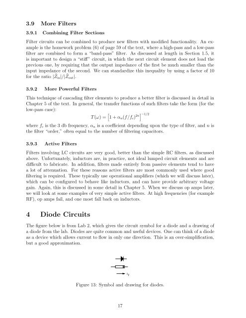
<strong>The</strong> figure below is from Lab 2, which gives the circuit symbol <strong>for</strong> a diode and a drawing of<br />
a diode from the lab. Diodes are quite common and useful devices. One can think of a diode<br />
as a device which allows current to flow in only one direction. This is an over-simplification,<br />
but a good approximation.<br />
Figure 13: Symbol and drawing <strong>for</strong> diodes.<br />
17<br />
I F


