

Lecture Notes for Analog Electronics - The Electronic Universe ...
Lecture Notes for Analog Electronics - The Electronic Universe ...
Lecture Notes for Analog Electronics - The Electronic Universe ...

You also want an ePaper? Increase the reach of your titles
YUMPU automatically turns print PDFs into web optimized ePapers that Google loves.
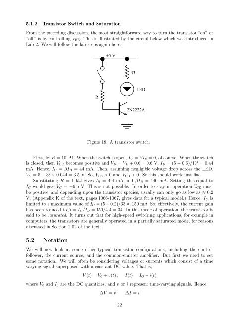
5.1.2 Transistor Switch and Saturation<br />
From the preceding discussion, the most straight<strong>for</strong>ward way to turn the transistor “on” or<br />
“off” is by controlling VBE. This is illustrated by the circuit below which was introduced in<br />
Lab 2. We will follow the lab steps again here.<br />
R<br />
+5 V<br />
33<br />
LED<br />
2N2222A<br />
Figure 18: A transistor switch.<br />
First, let R = 10 kΩ. When the switch is open, IC = βIB = 0, of course. When the switch<br />
is closed, then VBE becomes positive and VB = VE +0.6=0.6V.IB =(5−0.6)/10 4 =0.44<br />
mA. Hence, IC = βIB = 44 mA. <strong>The</strong>n, assuming negligible voltage drop across the LED,<br />
VC =5−33 × 0.044 = 3.5 V.So,VCE > 0andVCB > 0. So this should work just fine.<br />
Substituting R =1kΩgivesIB =4.4mAandβIB = 440 mA. Setting this equal to<br />
IC would give VC = −9.5 V. This is not possible. In order to stay in operation VCE must<br />
be positive, and depending upon the transistor species, usually can only go as low as ≈ 0.2<br />
V. (Appendix K of the text, pages 1066-1067, gives data <strong>for</strong> a typical model.) Hence, IC is<br />
limited to a maximum value of IC =(5−0.2)/33 ≈ 150 mA. So, effectively, the current gain<br />
has been reduced to β = IC/IB = 150/4.4 = 34. In this mode of operation, the transistor is<br />
said to be saturated. It turns out that <strong>for</strong> high-speed switching applications, <strong>for</strong> example in<br />
computers, the transistors are generally operated in a partially saturated mode, <strong>for</strong> reasons<br />
discussed in Section 2.02 of the text.<br />
5.2 Notation<br />
We will now look at some other typical transistor configurations, including the emitter<br />
follower, the current source, and the common-emitter amplifier. But first we need to set<br />
some notation. We will often be considering voltages or currents which consist of a time<br />
varying signal superposed with a constant DC value. That is,<br />
V (t) =V0+v(t); I(t)=IO+i(t)<br />
where V0 and I0 are the DC quantities, and v or i represent time-varying signals. Hence,<br />
∆V = v ; ∆I = i<br />
22


