

Lecture Notes for Analog Electronics - The Electronic Universe ...
Lecture Notes for Analog Electronics - The Electronic Universe ...
Lecture Notes for Analog Electronics - The Electronic Universe ...

Create successful ePaper yourself
Turn your PDF publications into a flip-book with our unique Google optimized e-Paper software.
Class <strong>Notes</strong> 6<br />
Following our discussion last time of the basic transistor switch and emitter follower, we<br />
will likewise introduce the basic relations <strong>for</strong> two other transistor circuit configurations: the<br />
current source and the common-emitter amplifier. We will then return to the issue of input<br />
and output impedance so that we can build realistic circuits using these configurations.<br />
5.4 Transistor Current Source<br />
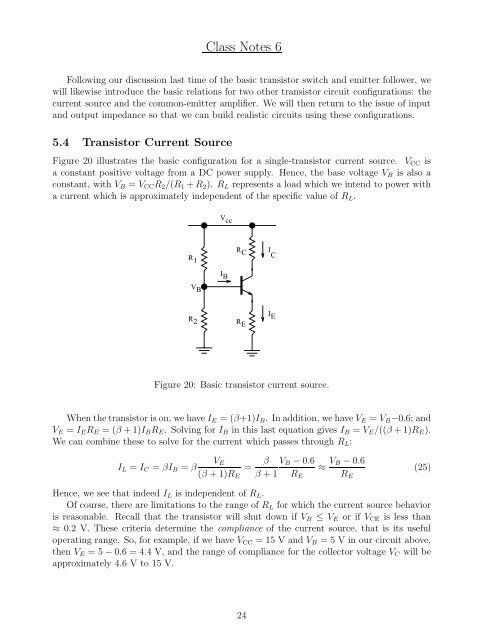
Figure 20 illustrates the basic configuration <strong>for</strong> a single-transistor current source. VCC is<br />
a constant positive voltage from a DC power supply. Hence, the base voltage VB is also a<br />
constant, with VB = VCCR2/(R1 + R2). RL represents a load which we intend to power with<br />
a current which is approximately independent of the specific value of RL.<br />
R 1<br />
V B<br />
R 2<br />
V cc<br />
I B<br />
R C<br />
R E<br />
Figure 20: Basic transistor current source.<br />
When the transistor is on, we have IE =(β+1)IB. In addition, we have VE = VB−0.6; and<br />
VE = IERE =(β+1)IBRE. Solving <strong>for</strong> IB in this last equation gives IB = VE/((β +1)RE).<br />
We can combine these to solve <strong>for</strong> the current which passes through RL:<br />
VE<br />
IL = IC = βIB = β =<br />
(β +1)RE<br />
β VB−0.6 ≈<br />
β+1 RE<br />
VB−0.6 (25)<br />
RE<br />
Hence, we see that indeed IL is independent of RL.<br />
Of course, there are limitations to the range of RL <strong>for</strong> which the current source behavior<br />
is reasonable. Recall that the transistor will shut down if VB ≤ VE or if VCE is less than<br />
≈ 0.2 V. <strong>The</strong>se criteria determine the compliance of the current source, that is its useful<br />
operating range. So, <strong>for</strong> example, if we have VCC =15VandVB = 5 V in our circuit above,<br />
then VE =5−0.6=4.4V, and the range of compliance <strong>for</strong> the collector voltage VC will be<br />
approximately 4.6 Vto15V.<br />
24<br />
I C<br />
I E


