

Lecture Notes for Analog Electronics - The Electronic Universe ...
Lecture Notes for Analog Electronics - The Electronic Universe ...
Lecture Notes for Analog Electronics - The Electronic Universe ...

Create successful ePaper yourself
Turn your PDF publications into a flip-book with our unique Google optimized e-Paper software.
1.2.1 Resistors in series<br />
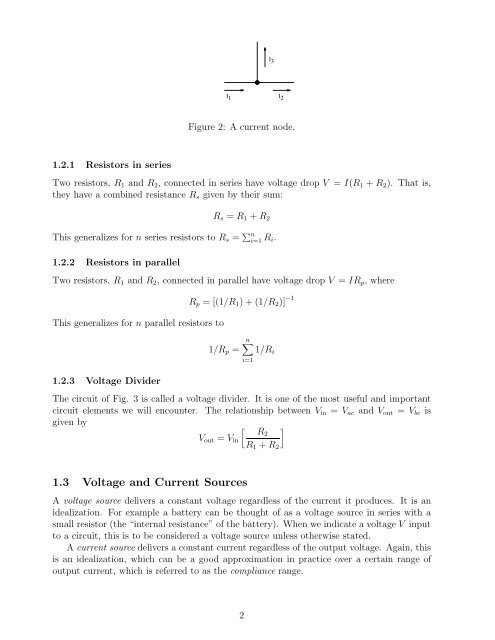
I3<br />
I1 I2<br />
Figure 2: A current node.<br />
Two resistors, R1 and R2, connected in series have voltage drop V = I(R1 + R2). That is,<br />
they have a combined resistance Rs given by their sum:<br />
Rs = R1 + R2<br />
This generalizes <strong>for</strong> n series resistors to Rs = � n i=1 Ri.<br />
1.2.2 Resistors in parallel<br />
Two resistors, R1 and R2, connected in parallel have voltage drop V = IRp, where<br />
This generalizes <strong>for</strong> n parallel resistors to<br />
1.2.3 Voltage Divider<br />
Rp=[(1/R1)+(1/R2)] −1<br />
n�<br />
1/Rp = 1/Ri<br />
i=1<br />
<strong>The</strong> circuit of Fig. 3 is called a voltage divider. It is one of the most useful and important<br />
circuit elements we will encounter. <strong>The</strong> relationship between Vin = Vac and Vout = Vbc is<br />
given by<br />
Vout = Vin<br />
1.3 Voltage and Current Sources<br />
� R2<br />
R1 + R2<br />
A voltage source delivers a constant voltage regardless of the current it produces. It is an<br />
idealization. For example a battery can be thought of as a voltage source in series with a<br />
small resistor (the “internal resistance” of the battery). When we indicate a voltage V input<br />
to a circuit, this is to be considered a voltage source unless otherwise stated.<br />
A current source delivers a constant current regardless of the output voltage. Again, this<br />
is an idealization, which can be a good approximation in practice over a certain range of<br />
output current, which is referred to as the compliance range.<br />
2<br />
�


