

Lecture Notes for Analog Electronics - The Electronic Universe ...
Lecture Notes for Analog Electronics - The Electronic Universe ...
Lecture Notes for Analog Electronics - The Electronic Universe ...

You also want an ePaper? Increase the reach of your titles
YUMPU automatically turns print PDFs into web optimized ePapers that Google loves.
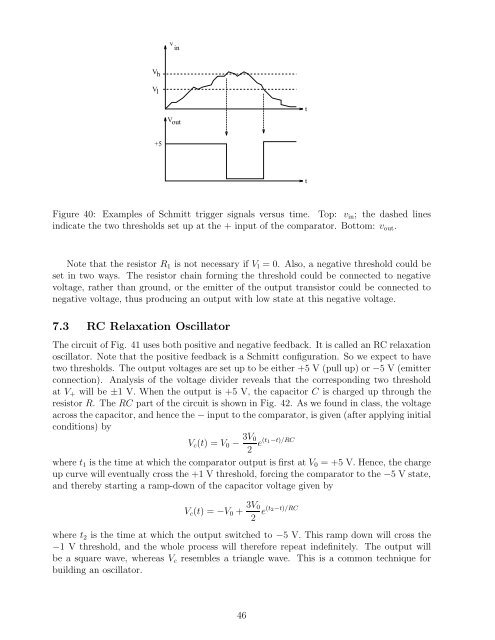
V h<br />
Vl<br />
+5<br />
v in<br />
V out<br />
Figure 40: Examples of Schmitt trigger signals versus time. Top: vin; the dashed lines<br />
indicate the two thresholds set up at the + input of the comparator. Bottom: vout.<br />
Note that the resistor R1 is not necessary if Vl = 0. Also, a negative threshold could be<br />
set in two ways. <strong>The</strong> resistor chain <strong>for</strong>ming the threshold could be connected to negative<br />
voltage, rather than ground, or the emitter of the output transistor could be connected to<br />
negative voltage, thus producing an output with low state at this negative voltage.<br />
7.3 RC Relaxation Oscillator<br />
<strong>The</strong> circuit of Fig. 41 uses both positive and negative feedback. It is called an RC relaxation<br />
oscillator. Note that the positive feedback is a Schmitt configuration. So we expect to have<br />
two thresholds. <strong>The</strong> output voltages are set up to be either +5 V (pull up) or −5 V (emitter<br />
connection). Analysis of the voltage divider reveals that the corresponding two threshold<br />
at V+ will be ±1 V. When the output is +5 V, the capacitor C is charged up through the<br />
resistor R. <strong>The</strong>RC part of the circuit is shown in Fig. 42. As we found in class, the voltage<br />
across the capacitor, and hence the − input to the comparator, is given (after applying initial<br />
conditions) by<br />
Vc(t) =V0− 3V0<br />
2 e(t1−t)/RC<br />
where t1 is the time at which the comparator output is first at V0 = +5 V. Hence, the charge<br />
up curve will eventually cross the +1 V threshold, <strong>for</strong>cing the comparator to the −5 Vstate,<br />
and thereby starting a ramp-down of the capacitor voltage given by<br />
Vc(t) =−V0+ 3V0<br />
2 e(t2−t)/RC<br />
where t2 is the time at which the output switched to −5 V.Thisrampdownwillcrossthe<br />
−1 V threshold, and the whole process will there<strong>for</strong>e repeat indefinitely. <strong>The</strong> output will<br />
be a square wave, whereas Vc resembles a triangle wave. This is a common technique <strong>for</strong><br />
building an oscillator.<br />
46<br />
t<br />
t


