

Lecture Notes for Analog Electronics - The Electronic Universe ...
Lecture Notes for Analog Electronics - The Electronic Universe ...
Lecture Notes for Analog Electronics - The Electronic Universe ...

You also want an ePaper? Increase the reach of your titles
YUMPU automatically turns print PDFs into web optimized ePapers that Google loves.
Perhaps the best way to beat these efects, if they are a problem <strong>for</strong> a particular application,<br />
is to choose op-amps which have good specifications. For example, IOS can be a<br />
problem <strong>for</strong> bi-polar designs, in which case choosing a design with FET inputs will usually<br />
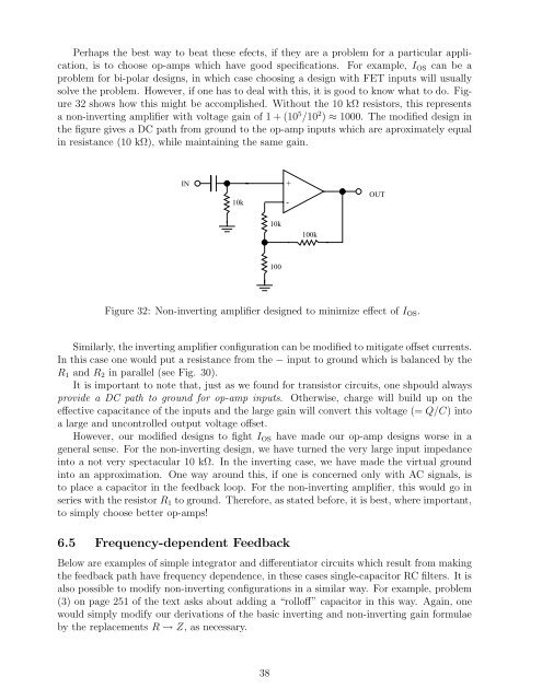
solve the problem. However, if one has to deal with this, it is good to know what to do. Figure<br />
32 shows how this might be accomplished. Without the 10 kΩ resistors, this represents<br />
a non-inverting amplifier with voltage gain of 1 + (10 5 /10 2 ) ≈ 1000. <strong>The</strong> modified design in<br />
the figure gives a DC path from ground to the op-amp inputs which are aproximately equal<br />
in resistance (10 kΩ), while maintaining the same gain.<br />
IN<br />
10k<br />
Figure 32: Non-inverting amplifier designed to minimize effect of IOS.<br />
Similarly, the inverting amplifier configuration can be modified to mitigate offset currents.<br />
In this case one would put a resistance from the − input to ground which is balanced by the<br />
R1 and R2 in parallel (see Fig. 30).<br />
It is important to note that, just as we found <strong>for</strong> transistor circuits, one shpould always<br />
provide a DC path to ground <strong>for</strong> op-amp inputs. Otherwise, charge will build up on the<br />
effective capacitance of the inputs and the large gain will convert this voltage (= Q/C) into<br />
a large and uncontrolled output voltage offset.<br />
However, our modified designs to fight IOS have made our op-amp designs worse in a<br />
general sense. For the non-inverting design, we have turned the very large input impedance<br />
into a not very spectacular 10 kΩ. In the inverting case, we have made the virtual ground<br />
into an approximation. One way around this, if one is concerned only with AC signals, is<br />
to place a capacitor in the feedback loop. For the non-inverting amplifier, this would go in<br />
series with the resistor R1 to ground. <strong>The</strong>re<strong>for</strong>e, as stated be<strong>for</strong>e, it is best, where important,<br />
to simply choose better op-amps!<br />
6.5 Frequency-dependent Feedback<br />
Below are examples of simple integrator and differentiator circuits which result from making<br />
the feedback path have frequency dependence, in these cases single-capacitor RC filters. It is<br />
also possible to modify non-inverting configurations in a similar way. For example, problem<br />
(3) on page 251 of the text asks about adding a “rolloff” capacitor in this way. Again, one<br />
would simply modify our derivations of the basic inverting and non-inverting gain <strong>for</strong>mulae<br />
by the replacements R → Z, as necessary.<br />
38<br />
10k<br />
100<br />
+<br />
-<br />
100k<br />
OUT


