

Lecture Notes for Analog Electronics - The Electronic Universe ...
Lecture Notes for Analog Electronics - The Electronic Universe ...
Lecture Notes for Analog Electronics - The Electronic Universe ...

Create successful ePaper yourself
Turn your PDF publications into a flip-book with our unique Google optimized e-Paper software.
1.5 <strong>The</strong>venin <strong>The</strong>orem (contd.)<br />
Class <strong>Notes</strong> 2<br />
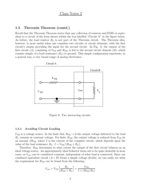
Recall that the <strong>The</strong>venin <strong>The</strong>orem states that any collection of resistors and EMFs is equivalent<br />
to a circuit of the <strong>for</strong>m shown within the box labelled “Circuit A” in the figure below.<br />
As be<strong>for</strong>e, the load resistor RL is not part of the <strong>The</strong>venin circuit. <strong>The</strong> <strong>The</strong>venin idea,<br />
however, is most useful when one considers two circuits or circuit elements, with the first<br />
circuit’s output providing the input <strong>for</strong> the second circuit. In Fig. 6, the output of the<br />
first circuit (A), consisitng of VTH and RTH, is fed to the second circuit element (B), which<br />
consists simply of a load resistance (RL) to ground. This simple configuration represents, in<br />
a general way, a very broad range of analog electronics.<br />
V TH<br />
Circuit A<br />
R TH<br />
1.5.1 Avoiding Circuit Loading<br />
Vout<br />
Figure 6: Two interacting circuits.<br />
Circuit B<br />
VTH is a voltage source. In the limit that RTH → 0 the output voltage delivered to the load<br />
RL remains at constant voltage. For finite RTH, the output voltage is reduced from VTH by<br />
an amount IRTH, whereIis the current of the complete circuit, which depends upon the<br />
value of the load resistance RL: I = VTH/(RTH + RL).<br />
<strong>The</strong>re<strong>for</strong>e, RTH determines to what extent the output of the first circuit behaves as an<br />
ideal voltage source. An approximately ideal behavior turns out to be quite desirable in most<br />
cases, as Vout can be considered constant, independent of what load is connected. Since our<br />
combined equivalent circuit (A + B) <strong>for</strong>ms a simple voltage divider, we can easily see what<br />
the requirement <strong>for</strong> RTH can be found from the following:<br />
�<br />
�<br />
RL<br />
Vout = VTH<br />
RTH + RL<br />
5<br />
=<br />
VTH<br />
1+(RTH/RL)<br />
R L


