

Lecture Notes for Analog Electronics - The Electronic Universe ...
Lecture Notes for Analog Electronics - The Electronic Universe ...
Lecture Notes for Analog Electronics - The Electronic Universe ...

You also want an ePaper? Increase the reach of your titles
YUMPU automatically turns print PDFs into web optimized ePapers that Google loves.
is low it will, after passing through an inverter, turn the transistor on. In this case, current<br />
sill pass through R and to the emitter connection. This current produces a voltage drop<br />
across R which pulls the output voltage (very close) to the emitter voltage (ground in our<br />
example). Typically R ≈ 1 kΩ. When the comparator inputs are in the complementary<br />
inequality, the transistor is switched off and the output voltage goes to the voltage held by<br />
R, which is +5 V in our example. Using outputs of 0 and +5 V are typical, since these<br />
voltages correspond (roughly) to the TTL convention of digital electronics.<br />
7.2 Schmitt Trigger<br />
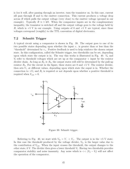
A typical circuit using a comparator is shown in Fig. 39. <strong>The</strong> output goes to one of its<br />
two possible states depending upon whether the input v− is greater than or less than the<br />
“threshold” determined by v+. Positive feedback is used to help rein<strong>for</strong>ce the chosen output<br />
state. In this configuration, called the Schmitt trigger, two thresholds can be set, depending<br />
upon which state the output is in. <strong>The</strong> way this works is illustrated in Fig. 40. Vh and<br />
Vl refer to threshold voltages which are set up at the comparator + input by the resistor<br />
divider chain. As long as R3 ≫ R4, the output states will still be determined by the pull-up<br />
resistor R4. For the circuit in the figure, these states are 0 and +5 V. <strong>The</strong> resistor divider,<br />
then sets V+ at different values, depending upon which state the ouput is in. Whether the<br />
connection to +V1 and R1 is required or not depends upon whether a positive threshold is<br />
required when Vout =0.<br />
v in<br />
R 1<br />
R 2<br />
+V 1<br />
-<br />
+<br />
R 3<br />
+5<br />
R 4<br />
Figure 39: Schmitt trigger.<br />
Referring to Fig. 40, we start with Vin = V−


