Lecture Notes for Analog Electronics - The Electronic Universe ...
Lecture Notes for Analog Electronics - The Electronic Universe ...
Lecture Notes for Analog Electronics - The Electronic Universe ...
You also want an ePaper? Increase the reach of your titles
YUMPU automatically turns print PDFs into web optimized ePapers that Google loves.
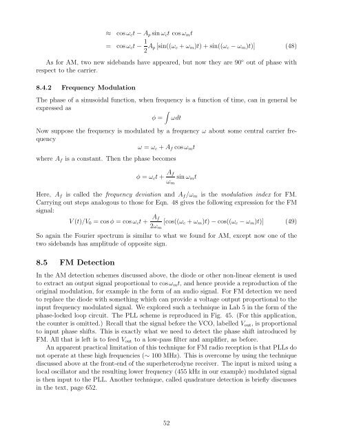
≈ cos ωct − Ap sin ωct cos ωmt<br />
= cosωct− 1<br />
2 Ap[sin((ωc + ωm)t)+sin((ωc−ωm)t)] (48)<br />
As <strong>for</strong> AM, two new sidebands have appeared, but now they are 90◦ out of phase with<br />
respect to the carrier.<br />
8.4.2 Frequency Modulation<br />
<strong>The</strong> phase of a sinusoidal function, when frequency is a function of time, can in general be<br />
expressed as<br />
�<br />
φ = ωdt<br />
Now suppose the frequency is modulated by a frequency ω about some central carrier frequency<br />
ω = ωc + Af cos ωmt<br />
where Af is a constant. <strong>The</strong>n the phase becomes<br />
φ = ωct + Af<br />
ωm<br />
sin ωmt<br />
Here, Af is called the frequency deviation and Af/ωm is the modulation index <strong>for</strong> FM.<br />
Carrying out steps analogous to those <strong>for</strong> Eqn. 48 gives the following expression <strong>for</strong> the FM<br />
signal:<br />
V (t)/V0 =cosφ=cosωct+ Af<br />
[cos((ωc + ωm)t) − cos((ωc − ωm)t)] (49)<br />
2ωm<br />
So again the Fourier spectrum is similar to what we found <strong>for</strong> AM, except now one of the<br />
two sidebands has amplitude of opposite sign.<br />
8.5 FM Detection<br />
In the AM detection schemes discussed above, the diode or other non-linear element is used<br />
to extract an output signal proportional to cos ωmt, and hence provide a reproduction of the<br />
original modulation, <strong>for</strong> example in the <strong>for</strong>m of an audio signal. For FM detection we need<br />
to replace the diode with something which can provide a voltage output proportional to the<br />
input frequency modulated signal. We explored such a technique in Lab 5 in the <strong>for</strong>m of the<br />
phase-locked loop circuit. <strong>The</strong> PLL scheme is reproduced in Fig. 45. (For this application,<br />
the counter is omitted.) Recall that the signal be<strong>for</strong>e the VCO, labelled Vout, is proportional<br />
to input phase shifts. This is exactly what we need to detect the phase shift introduced by<br />
FM. All that is left is to feed Vout to a low-pass filter and amplifier, as be<strong>for</strong>e.<br />
An apparent practical limitation of this technique <strong>for</strong> FM radio reception is that PLLs do<br />
not operate at these high frequencies (∼ 100 MHz). This is overcome by using the technique<br />
discussed above at the front-end of the superheterodyne receiver. <strong>The</strong> input is mixed using a<br />
local oscillator and the resulting lower frequency (455 kHz in our example) modulated signal<br />
is then input to the PLL. Another technique, called quadrature detection is briefly discusses<br />
in the text, page 652.<br />
52


