

Lecture Notes for Analog Electronics - The Electronic Universe ...
Lecture Notes for Analog Electronics - The Electronic Universe ...
Lecture Notes for Analog Electronics - The Electronic Universe ...

You also want an ePaper? Increase the reach of your titles
YUMPU automatically turns print PDFs into web optimized ePapers that Google loves.
In 1<br />
and similarly <strong>for</strong> output 2<br />
R C<br />
Out 1<br />
R E<br />
A<br />
VCC<br />
RE<br />
REE<br />
V<br />
EE<br />
R C<br />
Out 2<br />
In 2<br />
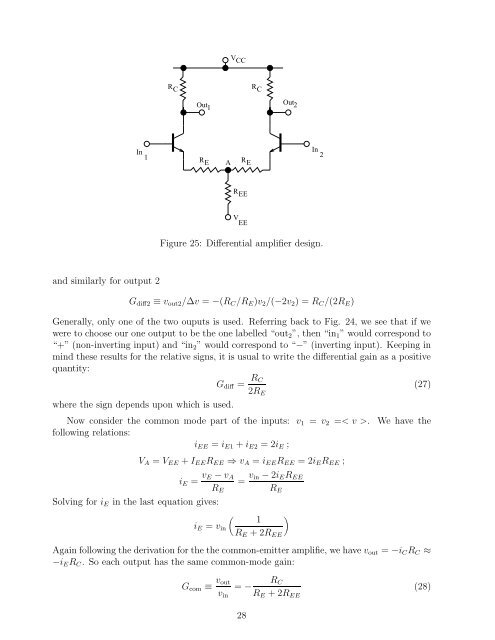
Figure 25: Differential amplifier design.<br />
Gdiff2 ≡ vout2/∆v = −(RC/RE)v2/(−2v2) =RC/(2RE)<br />
Generally, only one of the two ouputs is used. Referring back to Fig. 24, we see that if we<br />
were to choose our one output to be the one labelled “out2”, then “in1” would correspond to<br />
“+” (non-inverting input) and “in2” would correspond to “−” (inverting input). Keeping in<br />
mind these results <strong>for</strong> the relative signs, it is usual to write the differential gain as a positive<br />
quantity:<br />
Gdiff = RC<br />
2RE<br />
where the sign depends upon which is used.<br />
Now consider the common mode part of the inputs: v1<br />
following relations:<br />
iEE = iE1 + iE2 =2iE;<br />
= v2 =< v>. We have the<br />
VA =VEE + IEEREE ⇒ vA = iEEREE =2iEREE ;<br />
iE = vE − vA<br />
Solving <strong>for</strong> iE in the last equation gives:<br />
RE<br />
�<br />
iE = vin<br />
= vin − 2iEREE<br />
RE<br />
1<br />
RE +2REE<br />
Again following the derivation <strong>for</strong> the the common-emitter amplifie, we have vout = −iCRC ≈<br />
−iERC. So each output has the same common-mode gain:<br />
Gcom ≡ vout<br />
vin<br />
RC<br />
�<br />
= −<br />
RE +2REE<br />
28<br />
(27)<br />
(28)


