

Lecture Notes for Analog Electronics - The Electronic Universe ...
Lecture Notes for Analog Electronics - The Electronic Universe ...
Lecture Notes for Analog Electronics - The Electronic Universe ...

You also want an ePaper? Increase the reach of your titles
YUMPU automatically turns print PDFs into web optimized ePapers that Google loves.
6.5.1 Integrator<br />
Using the golden rules <strong>for</strong> the circuit of Fig. 33, we have<br />
vin − v−<br />
=<br />
R<br />
vin<br />
R = iin = iout = −C d(vout − v−)<br />
= −C<br />
dt<br />
dvout<br />
dt<br />
So, solving <strong>for</strong> the output gives<br />
vout = − 1<br />
�<br />
vindt (38)<br />
RC<br />
And <strong>for</strong> a single Fourier component ω, this gives <strong>for</strong> the gain<br />
G(ω) =− 1<br />
(39)<br />
ωRC<br />
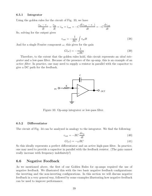
<strong>The</strong>re<strong>for</strong>e, to the extent that the golden rules hold, this circuit represents an ideal integrator<br />
and a low-pass filter. Because of the presence of the op-amp, this is an example of an<br />
active filter. In practice, one may need to supply a resistor in parallel with the capacitor to<br />
give a DC path <strong>for</strong> the feedback.<br />
6.5.2 Differentiator<br />
IN<br />
R<br />
-<br />
+<br />
C<br />
OUT<br />
Figure 33: Op-amp integrator or low-pass filter.<br />
<strong>The</strong> circuit of Fig. 34 can be analyzed in analogy to the integrator. We find the following:<br />
vout = −RC dvin<br />
(40)<br />
dt<br />
G(ω) =−ωRC (41)<br />
So this ideally represents a perfect differentiator and an active high-pass filter. In practice,<br />
one may need to provide a capacitor in parallel with the feedback resistor. (<strong>The</strong> gain cannot<br />
really increase with frequency indefinitely!)<br />
6.6 Negative Feedback<br />
As we mentioned above, the first of our Golden Rules <strong>for</strong> op-amps required the use of<br />
negative feedback. We illustrated this with the two basic negative feedback configurations:<br />
the inverting and the non-inverting configurations. In this section we will discuss negative<br />
feedback in a very general way, followed by some examples illustrating how negative feedback<br />
can be used to improve per<strong>for</strong>mance.<br />
39


