Lecture Notes for Analog Electronics - The Electronic Universe ...
Lecture Notes for Analog Electronics - The Electronic Universe ...
Lecture Notes for Analog Electronics - The Electronic Universe ...
You also want an ePaper? Increase the reach of your titles
YUMPU automatically turns print PDFs into web optimized ePapers that Google loves.
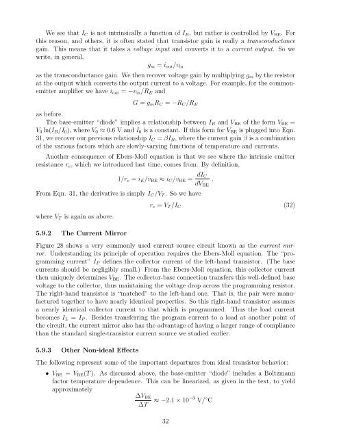
We see that IC is not intrinsically a function of IB, but rather is controlled by VBE. For<br />
this reason, and others, it is often stated that transistor gain is really a transconductance<br />
gain. This means that it takes a voltage input and converts it to a current output. So we<br />
write, in general,<br />
gm = iout/vin<br />
as the transconductance gain. We then recover voltage gain by multiplying gm by the resistor<br />
at the output which converts the output current to a voltage. For example, <strong>for</strong> the commonemitter<br />
amplifier we have iout = −vin/RE and<br />
G = gmRC = −RC/RE<br />
as be<strong>for</strong>e.<br />
<strong>The</strong> base-emitter “diode” implies a relationship between IB and VBE of the <strong>for</strong>m VBE =<br />
V0 ln(IB/I0), where V0 ≈ 0.6 VandI0is a constant. If this <strong>for</strong>m <strong>for</strong> VBE is plugged into Eqn.<br />
31, we recover our previous relationship IC = βIB, where the current gain β is a combination<br />
of the various factors which are slowly-varying functions of temperature and currents.<br />
Another consequence of Ebers-Moll equation is that we see where the intrinsic emitter<br />
resistance re, which we introduced last time, comes from. By definition,<br />
1/re = iE/vBE ≈ iC/vBE = dIC<br />
From Eqn. 31, the derivative is simply IC/VT .Sowehave<br />
where VT is again as above.<br />
5.9.2 <strong>The</strong> Current Mirror<br />
re=VT/IC<br />
dVBE<br />
Figure 28 shows a very commonly used current source circuit known as the current mirror.<br />
Understanding its principle of operation requires the Ebers-Moll equation. <strong>The</strong> “programming<br />
current” IP defines the collector current of the left-hand transistor. (<strong>The</strong> base<br />
currents should be negligibly small.) From the Ebers-Moll equation, this collector current<br />
then uniquely determines VBE. <strong>The</strong> collector-base connection transfers this well-defined base<br />
voltage to the collector, thus maintaining the voltage drop across the programming resistor.<br />
<strong>The</strong> right-hand transistor is “matched” to the left-hand one. That is, the pair were manufactured<br />
together to have nearly identical properties. So this right-hand transistor assumes<br />
a nearly identical collector current to that which is programmed. Thus the load current<br />
becomes IL = IP . Besides transferring the program current to a load at another point of<br />
the circuit, the current mirror also has the advantage of having a larger range of compliance<br />
than the standard single-transistor current source we studied earlier.<br />
5.9.3 Other Non-ideal Effects<br />
<strong>The</strong> following represent some of the important departures from ideal transistor behavior:<br />
• VBE = VBE(T ). As discussed above, the base-emitter “diode” includes a Boltzmann<br />
factor temperature dependence. This can be linearized, as given in the text, to yield<br />
approximately<br />
∆VBE<br />
∆T ≈−2.1×10⁻³ V/ ◦ C<br />
32<br />
.<br />
(32)


