

Lecture Notes for Analog Electronics - The Electronic Universe ...
Lecture Notes for Analog Electronics - The Electronic Universe ...
Lecture Notes for Analog Electronics - The Electronic Universe ...

Create successful ePaper yourself
Turn your PDF publications into a flip-book with our unique Google optimized e-Paper software.
f c<br />
+<br />
+<br />
f m<br />
V s<br />
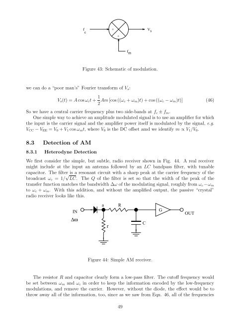
Figure 43: Schematic of modulation.<br />
we can do a “poor man’s” Fourier trans<strong>for</strong>m of Vs:<br />
Vs(t) =Acos ωct + 1<br />
2 Am [cos ((ωc + ωm)t)+cos((ωc−ωm)t)] (46)<br />
So we have a central carrier frequency plus two side-bands at fc ± fm.<br />
One simple way to achieve an amplitude modulated signal is to use an amplifier <strong>for</strong> which<br />
the input is the carrier signal and the amplifier power itself is modulated by the signal, e.g.<br />
VCC − VEE = V0 + V1 cos ωmt, whereV0is the DC offset amd we identify m ∝ V1/V0.<br />
8.3 Detection of AM<br />
8.3.1 Heterodyne Detection<br />
We first consider the simple, but subtle, radio receiver shown in Fig. 44. A real receiver<br />
might include at the input an antenna followed by an LC bandpass filter, with tunable<br />
capacitor. <strong>The</strong> filter is a resonant circuit with a sharp peak at the carrier frequency of the<br />
broadcast ωc =1/ √ LC. <strong>The</strong> Q of the filter is set so that the width of the peak of the<br />
transfer function matches the bandwidth ∆ω of the modulating signal, roughly from ωc −ωm<br />
to ωc + ωm. With this addition, and without the amplified output, the passive “crystal”<br />
radio receiver looks like this.<br />
a R<br />
IN G<br />
OUT<br />
Δω<br />
r<br />
Figure 44: Simple AM receiver.<br />
<strong>The</strong> resistor R and capacitor clearly <strong>for</strong>m a low-pass filter. <strong>The</strong> cutoff frequency would<br />
be set between ωm and ωc in order to keep the in<strong>for</strong>mation encoded by the low-frequency<br />
modulations, and remove the carrier. However, without the diode, the effect would be to<br />
throw away all of the in<strong>for</strong>mation, too, since as we saw from Eqn. 46, all of the frequencies<br />
49<br />
C


