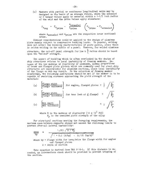
-26-(c)Members with partial or continuous longitudinal welds maybe<strong>design</strong>ed on the basis of an average stress, where the annealedor O temper values apply to material within a 1-1/2 inch radiusof the weld and the prime values apply elsewhere:AannealedFc =Fc-—Fc - Fcavg prime ‘prime prime annealed()where Aamea~ed and Apr~e are the respective cross sectionalareas.Similar <strong>considerations</strong> could be applied to the <strong>design</strong> of <strong>aluminum</strong>plate panels subject to compressive buckling loads. In general, weldingdoes not affect the buckling characteristics of plate panels, since thereis seldom welding in the middle of a panel. However, <strong>for</strong> welded <strong>aluminum</strong>bstructure, the cut-off panel strength <strong>for</strong> low k ~ ratios should be basedupon the ‘JweldediJstrength.One aspect of buckling which is often overlooked in the <strong>design</strong> ofship <strong>structures</strong> relates to local instability of fr~ing members. Becauseof the low modulus of elasticity of al~inuj norm~ ProPOr~iO~of beams and flanged plate girders which are commofiy used <strong>for</strong> steel~ship<strong>structures</strong> are unacceptable <strong>for</strong> <strong>aluminum</strong> sections, since local instabilityof th~ flange or web may result. In the selection of framing memberscantlingsj the following limitations should be.met if the member is to becapable of resisting stresses approaching the yield strength of thematerial:(a) ~~~~$ness <strong>for</strong>[ 1(b)Flange widthFlange thickness[1<strong>for</strong>where E is the modulus of elasticity (10 x 106 PSI)I?yis the unwelded yield strength of the alloyFor structural sections meeting themaximum span between supports should notprevent over-all lateral instability:<strong>for</strong>egoing requirements, theexceed the following limits toT 57.283 ~~1 +0.2 (d/bF) - 0.128 (bF/d)2where bF = flange width <strong>for</strong> tees;twice the flange width <strong>for</strong> anglesand flanged platesd = depth of sec”hionThis equation is derived fromDDS 9110-4. If this distance is exshouldbe provided to prevent tripping ofceeded, an intermediate chockthe section..—
-27-Corrosion ResistanceThe S000 series <strong>aluminum</strong> magnesium alloys are generally considered tohave excellent resistance to corrosion in a salt air~salt water environmentif reasonable precautions are taken tO protect the metq. l’hecharacteristics of <strong>aluminum</strong> which might lead to corrosion are well documented,References (39) through (45). The following paragraphs brieflysummarize the potential types of corrosion and the conditions leading tothem.Galvanic Corrosion is caused by dissimilar metals in contact in thepresence of an electrolyte such as salt water. Alumirnm is generallyanodic to other materials ad will be the metal to corrode. This corrosionis due to the different potential in electrical contact between the metals,which results in the transfer of ions through the electrolyte. Hullcathodic protection can be provided by sacrificial zinc or “<strong>aluminum</strong>anodeson the shell, bilge areas, piping systems in,tanks and sea chests or animpressed current system, as discussed later.Deposition Corrosion is a special case of galvanic corrosion whereparticles of the more noble metal are deposited on the <strong>aluminum</strong>, whichthen pits. Copper and mercury are particularly bad in this respect, andcontact of <strong>aluminum</strong> with these metals should be avoided.Crevice Corrosion results from trapped water in crevices causingpitting due to the anodic reaction between the o~gen-free water deep inthe crevice ad the oxygen-saturatedwater at the mouth of the crevice.Crevice corrosion canbe avoided by eliminating pockets, crevices, lappedjoints and other similar conditions where water can become trapped. Inareas where such a condition is unavoidable, such as the faying surfacebetween <strong>aluminum</strong> foundations and eq-uipment,the <strong>aluminum</strong> sur~ace should beprotected with a suitable paint system.or sealant.Pitting Corrosion occurs in water when only a small area of protectiveoxide or paint is removed from the <strong>aluminum</strong> surface. Once started, thepitting teds to continue, though at a diminishing rate. The damage to the<strong>aluminum</strong> oxide film is self-healing, even undezwater~ However, the loss inpaint area might not be repaired <strong>for</strong> a long period of time. This leads tothe conclusion that painting of the <strong>aluminum</strong> structure should be avoidedexcept where required, such as anti-fouling paint <strong>for</strong> the bottom. Asrecommended later, a cathodic protection system is recommended to preventpitting corros~on in way of scratched anti-fouling paint.Stress Corrosion is cracking which occurs over a period of time as aresult of a susceptible metallurgical structure, sustained surface tensilestress and a corrosive environment. The imposed stresses may be residualOY externally applied. In strain-hardenedA1-Mg alloys, precipitationoccurs over the years, and in h~gh-magnesium alloys (over h per cent)}this suscepbibilikymay develop in 5 to 10 years or less. Susceptibilityto stress corrosion cracking (SCC) becomes worse at elevated temperatures.Reference (43) notes the following relative to S000 series alloys: 5052,5252 and ~b~hhave low susceptibility to SCC, and~4~4 (Mg content 2.7per cent) has low susceptibility at temperatures above 1~0 degrees 1?.Alloy ~1~~ (l& content j.~ per cent) is satisfactory at room temperature,but not at temperatures above 150 degrees F. Alloy 5086 (Mg content 4.0per cent} is similar to 5154.
- Page 5: CONTENTSI.. II.III.Iv.v.VI ●VII.I
- Page 9 and 10: LIST OF FIGURES(Cent’d)FIGURE NO.
- Page 11 and 12: I. INTRODUCTIONThis report summariz
- Page 13: art in fabricating and maintaining
- Page 16 and 17: MONTEROSSO GRANA /17VALGRANA / CARA
- Page 18 and 19: -8-Numerous references have been re
- Page 20 and 21: .10.TABLE 2. Mechanical Properties
- Page 22 and 23: TABLE 2 Mechanical Properties of Al
- Page 24 and 25: TABLE 3 Mechanical Property Limits
- Page 26 and 27: -16-l?igures5, 6, 7 ati 8 present f
- Page 28 and 29: -18-ti-’”’-”-””””-L
- Page 30 and 31: -20-60 .r---.— ..,.— -——,L-
- Page 32 and 33: .22-each stress level, rate of load
- Page 34 and 35: -24-!Z456-H321 = 0.485083-H321 = 0.
- Page 38 and 39: -28-AllOyS 5083 and 54.56(~ content
- Page 40 and 41: -30-The previous paragraphs have de
- Page 42 and 43: -32-The problem of cargo hold abras
- Page 44 and 45: -34-The question of residual stress
- Page 46 and 47: .36-Each alloy was given a relative
- Page 48 and 49: -38-GENERAL OBSERVATIONSFYior to a
- Page 50 and 51: -40-The question of comparative imp
- Page 52 and 53: -42-(d)(e)Poor quality welds due to
- Page 54 and 55: -44-The ABS criteria noted above we
- Page 56 and 57: -46-DNV would consider fatigue in e
- Page 58 and 59: -48-is less, for the exposed side s
- Page 60 and 61: Equation (2):-50-Hu1l SMa~um = Hull
- Page 62 and 63: -52-Another aspect of vibrations wh
- Page 64 and 65: -54-000000000Bottom Shell PlateSide
- Page 66 and 67: -56-at the deck and keel. This stre
- Page 68 and 69: -58-AT is the change inUT= Thermal
- Page 70 and 71: -60-SUl@!ARYAll parties contacted f
- Page 72 and 73: -62-(c)(d)(e)(f)T~e exterior side o
- Page 74 and 75: TABLE 12 Aluminum Bulk Carrier - Su
- Page 76 and 77: .66-INSUT.ATION AND SHEATHINGShell8
- Page 78 and 79: -68-(b)(c)(d)(e)(f)(g)(h)(i)(j)At l
- Page 80 and 81: -70-IIF.INSTALLATION OF SYSTEMS AND
- Page 82 and 83: Rudder Assembly -carrier should be
- Page 84 and 85: -74-(b)MechanicalTensile Strength 6
- Page 86 and 87:
-76-(e)The steel piping must be of
- Page 88 and 89:
-78-Other Piping Systems and Valves
- Page 90 and 91:
-80-struetion for the aluminum hull
- Page 92 and 93:
-82-Large heavy type machine~ must
- Page 94 and 95:
suffers attack in an alkaline envir
- Page 96 and 97:
-86-REPAIRSObtaining proper repairs
- Page 98 and 99:
-88-The design of the midship s~cti
- Page 100 and 101:
-90-assuming the increase is applic
- Page 102 and 103:
LIGHT SHIP WEIGHT ESTIMATE-92-In or
- Page 104 and 105:
-94-TABLE 20 Aluminum Bulk Carrier
- Page 106 and 107:
TABLE 22 Trim and StabilityFull Loa
- Page 108 and 109:
-98-TABLE 24 Price of Steel Bulk Ca
- Page 110 and 111:
GaseNumber. . . -.,- .TABLE 27 Comp
- Page 112 and 113:
-1o2-TABLE 28CarriersComparison of
- Page 114 and 115:
12 ---n..T.[T7%l,=LEGS IU ORF=ErY
- Page 116 and 117:
-106-such as iron ore, on two of th
- Page 118 and 119:
-108-7)is,zg~ gg~5e mzz~E’4E!~K2j
- Page 120 and 121:
-11o-(a)(b)(c)(d)Inerting system fo
- Page 122 and 123:
-112-fatigue, particularly in the p
- Page 124 and 125:
-114-2k* Installation of Systems an
- Page 126 and 127:
-116-LIST OF REFERENCES(7)Fatigue P
- Page 128 and 129:
-11.8-LLST OF REFERENCES(Cent’d)(
- Page 130 and 131:
-120-ADDITIONAL SOURCES OF INFORMAT
- Page 132 and 133:
-122-redistribution of the still wa
- Page 134 and 135:
-124-APPENDIX BEXCERPTS FROMRULES A
- Page 136 and 137:
-126-92.07-10(d)(~) Interior stairs
- Page 138 and 139:
-128-~gE1+0102030- .. ..—405060
- Page 140 and 141:
ectintyclassification4KEYWORDSROLEL
- Page 142:
SHIP STRUCTURE COMMITTEE PUBLICATIO


