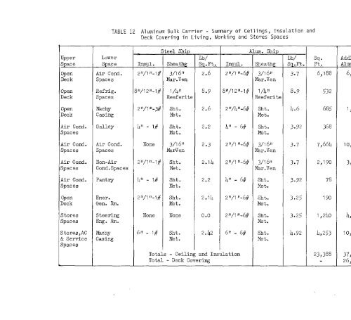
TABLE 12 Aluminum Bulk Carrier - Summary of Ceilings, Insulation andDeck Covering in Living, Ilorking and S~o~es SpacesSteel <strong>Ship</strong>Alum. <strong>Ship</strong>Upper Lower Lb/ Lb/ Sq ● AddlSpace Space Insul. Sheathg Sq.Ft. Iklsul. Sheathg Sq.Ft. Ft. AlumOpen Air Cond. 2rf\~ff-1# 3/16” 2.6 2!1/~f!-6# 3/16J’ 3*7 6,188 6,Deck Spaces Mar.Ven Mar.VenOpen Refrig. 8J)/12Jl-1# 1/4JJ 8.9 811\1211-~# 1/~II 8.9 5’32Deck Spaces Reeferite ReeferiteOpen Machy 21i/111-3# Sht. 2.6 2t!\4fI-6# Shb. 4.6 685 1,Deck Casing wt. Met.Air Cond. Galley ~11 - 1# Sht. 2.2 411 - 6# Sht. 3.92 368Spaces Met. Met.Air Cond. Air Cond. None 3/161’ 2.3 2’1\I’1-6# 3/16“ 3.7 7,6f5h 10,Spaces Spaces MarVen I%r.VenAir Cond. Non-Air 211/lIl_l# Sht . 2.14 2f1/~!l-6# 3/16“ 3*7 2,190 3,Spaces Cond.Spaces Met. Mar.VenAir Cond. Pantry 411-1# Sht. 2.2 41! - 6# Sht . 3.92 785paces Met. Met.Cpen Emer. 21t/lIl_~# Sht . 2.I4 2!I\-l If-6# Sht . 3.25 190Deck Gen. Rm. Met. Met.Stores Steering None None 0.0 2JI/lH-6# Sht. 3.25 I,240 4,Spaces E@. Rm. Met.3tores,AC Machy 6N - 1# Sht . 2.42 6I! - 6# Sht* 4.92 4,253 10,% Service Casing Met. Met.3pacesTotals - Ceiling and Insulation 23,388 37,Total - Deck Covering 26,
.65-Machineq Spaces - Reference (68) lists 24s fire casualties on allclasses of ships, of which only four were on bulk carriers. Three of thefour fires originated in themachineryspaces and one in the accommodationspaces. Of those occurring in the machinery spaces, two were the resultof fuel oil fires while combustible materials restite’din the accommodationspace fire. This agrees with the expected assumption that these two t~esof combustibles are the primary sources of incipient fires, and that theselocations must there<strong>for</strong>e be provided with the maximum protection againstfires.Within the machine~ space, the most serious problem is the protectionof the exposed <strong>aluminum</strong> structure to prevent the passage of smoke and flameand to restrict the maximum temperature of the <strong>aluminum</strong> to 400 degrees F<strong>for</strong> the required one hour time interval. The overriding requirement is themaximum temperature restriction in the presence of fire, since if this canbe accomplished, the structure will prevent the passage of smoke and flame.One potential solution might be the use of sprinklers to <strong>for</strong>m water wallson the vertical surfaces and the underside of the flats. However, thismethod is incompatiblewith an oil fire. A fixed fog system might be consideredbut to date there have been no physical tests to evaluate the timetemperatureresults of either of these proposals. A simple solution wouldbe to constmct the machinew space enclosing structure of stieel. This,however, poses additional problems of added weight, connection of incompatiblemetals, and differential coefficients of expansion. For many local<strong>structures</strong>, such as machinery flats and small tanks, the use of steel inlieu of protected <strong>aluminum</strong> would appear to offer significant cost savingswithout a major weight penalty. Various types of fire-retardant intumescentpaints are available, but these are p~imarily used to retard the sPread offire rather tha to restrict the temperature rise on the surface to whichthey are applied <strong>for</strong> any appreciable time duration.Of all the methods considered, the one chosen to best provide thedesired protection to vertical surfaces and the crown of the machinery boxis the application of a suitable thickness of insulation, sheathed with metalto protect the insulation against injury and abrasion.The surface of tank top, while still requiring the same degree of protection,presents a rather different problem due to personnel access and abrasionfrom the movement of equipment. Of all the available materials considered, acomposite construction consisting of an approved cellular glass incombustiblematerial, expanded metal, .%bkote No. 1 and a magnesia aggregate topping similarto MIG-11-2313Lhas been selected as the optimum after due consideration ofweight, cost. abrasion, resistance, oil spillage, good housekeep~ng and otherconstraints.Table 13 gives the approximate areas in each category together withthe anticipated approximate added weight to protect the <strong>aluminum</strong>.While not considered in detail at this time, other items that must bedealt with are structural stanchions and webs in the machine~ spaces,together with exposed areas of main and auxilia~ machine~ foundations.It is also necessa~ to offset the deleterious effects of heat tramfer,
- Page 5:
CONTENTSI.. II.III.Iv.v.VI ●VII.I
- Page 9 and 10:
LIST OF FIGURES(Cent’d)FIGURE NO.
- Page 11 and 12:
I. INTRODUCTIONThis report summariz
- Page 13:
art in fabricating and maintaining
- Page 16 and 17:
MONTEROSSO GRANA /17VALGRANA / CARA
- Page 18 and 19:
-8-Numerous references have been re
- Page 20 and 21:
.10.TABLE 2. Mechanical Properties
- Page 22 and 23:
TABLE 2 Mechanical Properties of Al
- Page 24 and 25: TABLE 3 Mechanical Property Limits
- Page 26 and 27: -16-l?igures5, 6, 7 ati 8 present f
- Page 28 and 29: -18-ti-’”’-”-””””-L
- Page 30 and 31: -20-60 .r---.— ..,.— -——,L-
- Page 32 and 33: .22-each stress level, rate of load
- Page 34 and 35: -24-!Z456-H321 = 0.485083-H321 = 0.
- Page 36 and 37: -26-(c)Members with partial or cont
- Page 38 and 39: -28-AllOyS 5083 and 54.56(~ content
- Page 40 and 41: -30-The previous paragraphs have de
- Page 42 and 43: -32-The problem of cargo hold abras
- Page 44 and 45: -34-The question of residual stress
- Page 46 and 47: .36-Each alloy was given a relative
- Page 48 and 49: -38-GENERAL OBSERVATIONSFYior to a
- Page 50 and 51: -40-The question of comparative imp
- Page 52 and 53: -42-(d)(e)Poor quality welds due to
- Page 54 and 55: -44-The ABS criteria noted above we
- Page 56 and 57: -46-DNV would consider fatigue in e
- Page 58 and 59: -48-is less, for the exposed side s
- Page 60 and 61: Equation (2):-50-Hu1l SMa~um = Hull
- Page 62 and 63: -52-Another aspect of vibrations wh
- Page 64 and 65: -54-000000000Bottom Shell PlateSide
- Page 66 and 67: -56-at the deck and keel. This stre
- Page 68 and 69: -58-AT is the change inUT= Thermal
- Page 70 and 71: -60-SUl@!ARYAll parties contacted f
- Page 72 and 73: -62-(c)(d)(e)(f)T~e exterior side o
- Page 76 and 77: .66-INSUT.ATION AND SHEATHINGShell8
- Page 78 and 79: -68-(b)(c)(d)(e)(f)(g)(h)(i)(j)At l
- Page 80 and 81: -70-IIF.INSTALLATION OF SYSTEMS AND
- Page 82 and 83: Rudder Assembly -carrier should be
- Page 84 and 85: -74-(b)MechanicalTensile Strength 6
- Page 86 and 87: -76-(e)The steel piping must be of
- Page 88 and 89: -78-Other Piping Systems and Valves
- Page 90 and 91: -80-struetion for the aluminum hull
- Page 92 and 93: -82-Large heavy type machine~ must
- Page 94 and 95: suffers attack in an alkaline envir
- Page 96 and 97: -86-REPAIRSObtaining proper repairs
- Page 98 and 99: -88-The design of the midship s~cti
- Page 100 and 101: -90-assuming the increase is applic
- Page 102 and 103: LIGHT SHIP WEIGHT ESTIMATE-92-In or
- Page 104 and 105: -94-TABLE 20 Aluminum Bulk Carrier
- Page 106 and 107: TABLE 22 Trim and StabilityFull Loa
- Page 108 and 109: -98-TABLE 24 Price of Steel Bulk Ca
- Page 110 and 111: GaseNumber. . . -.,- .TABLE 27 Comp
- Page 112 and 113: -1o2-TABLE 28CarriersComparison of
- Page 114 and 115: 12 ---n..T.[T7%l,=LEGS IU ORF=ErY
- Page 116 and 117: -106-such as iron ore, on two of th
- Page 118 and 119: -108-7)is,zg~ gg~5e mzz~E’4E!~K2j
- Page 120 and 121: -11o-(a)(b)(c)(d)Inerting system fo
- Page 122 and 123: -112-fatigue, particularly in the p
- Page 124 and 125:
-114-2k* Installation of Systems an
- Page 126 and 127:
-116-LIST OF REFERENCES(7)Fatigue P
- Page 128 and 129:
-11.8-LLST OF REFERENCES(Cent’d)(
- Page 130 and 131:
-120-ADDITIONAL SOURCES OF INFORMAT
- Page 132 and 133:
-122-redistribution of the still wa
- Page 134 and 135:
-124-APPENDIX BEXCERPTS FROMRULES A
- Page 136 and 137:
-126-92.07-10(d)(~) Interior stairs
- Page 138 and 139:
-128-~gE1+0102030- .. ..—405060
- Page 140 and 141:
ectintyclassification4KEYWORDSROLEL
- Page 142:
SHIP STRUCTURE COMMITTEE PUBLICATIO