

Electronic Devices and Amplifier Circuits
Electronic Devices and Amplifier Circuits - Orchard Publications
Electronic Devices and Amplifier Circuits - Orchard Publications

You also want an ePaper? Increase the reach of your titles
YUMPU automatically turns print PDFs into web optimized ePapers that Google loves.
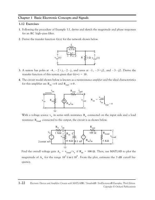
Chapter 1 Basic <strong>Electronic</strong> Concepts <strong>and</strong> Signals1.12 Exercises1. Following the procedure of Example 1.1, derive <strong>and</strong> sketch the magnitude <strong>and</strong> phase responsesfor an RC high−pass filter.2. Derive the transfer function Gs ( ) for the network shown below.+v in () t−CL0.5 H+ − +1 FR1 Ωv out () t−3. A system has poles at – 4 , – 2 + j, – 2 – j, <strong>and</strong> zeros at – 1 , – 3 + j2, <strong>and</strong> – 3 – j2. Derive thetransfer function of this system given that G( ∞) = 10 .4. The circuit model shown below is known as a transresistance amplifier <strong>and</strong> the ideal characteristicsfor this amplifier are R in → 0 <strong>and</strong> R out → 0 .i inR outv ini outv outv outR R in in = ---------iR in i inini out= 0With a voltage source in series with resistance connected on the input side <strong>and</strong> a loadv sresistance connected to the output, the circuit is as shown below.R sR load+v S2cosωt mV+−R Si in1 KΩ + v in−R in C−10 KΩ 0.1 nFR out100 Ω R loadR m i m5 KΩ+v load−Find the overall voltage gain A v = v load ⁄ v sif R m = 100 Ω . Then, use MATLAB to plot themagnitude of A vfor the range 10 3 ≤ω ≤10 8 . From the plot, estimate the 3 dB cutoff frequency.1−22<strong>Electronic</strong> <strong>Devices</strong> <strong>and</strong> <strong>Amplifier</strong> <strong>Circuits</strong> with MATLAB® / Simulink® / Sim<strong>Electronic</strong>s® Examples, Third EditionCopyright © Orchard Publicationss


