

Electronic Devices and Amplifier Circuits
Electronic Devices and Amplifier Circuits - Orchard Publications
Electronic Devices and Amplifier Circuits - Orchard Publications

Create successful ePaper yourself
Turn your PDF publications into a flip-book with our unique Google optimized e-Paper software.
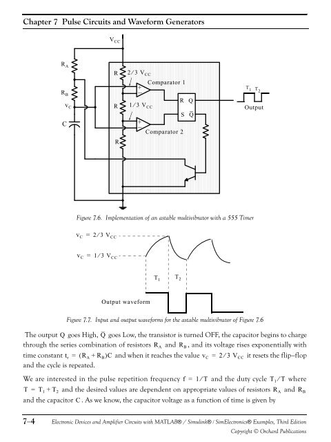
Chapter 7 Pulse <strong>Circuits</strong> <strong>and</strong> Waveform GeneratorsV CCR AR Bv CCRR2 ⁄ 3 V CCComparator 1+R1 ⁄ 3 V CCS+Comparator 2QQT 1 T 2OutputRFigure 7.6. Implementation of an astable multivibrator with a 555 Timerv C = 2 ⁄ 3 V CCv C = 1 ⁄ 3 V CCT 1T 2Output waveformFigure 7.7. Input <strong>and</strong> output waveforms for the astable multivibrator of Figure 7.6The output Q goes High, Q goes Low, the transistor is turned OFF, the capacitor begins to chargethrough the series combination of resistors R A <strong>and</strong> R B , <strong>and</strong> its voltage rises exponentially withtime constant t r = ( R A + R B )C <strong>and</strong> when it reaches the value v C = 2 ⁄ 3 V CC it resets the flip−flop<strong>and</strong> the cycle is repeated.We are interested in the pulse repetition frequency f = 1⁄T <strong>and</strong> the duty cycle T 1 ⁄ T whereT = T 1 + T 2 <strong>and</strong> the desired values are dependent on appropriate values of resistors R A <strong>and</strong> R B<strong>and</strong> the capacitor C . As we know, the capacitor voltage as a function of time is given by7−4<strong>Electronic</strong> <strong>Devices</strong> <strong>and</strong> <strong>Amplifier</strong> <strong>Circuits</strong> with MATLAB® / Simulink® / Sim<strong>Electronic</strong>s® Examples, Third EditionCopyright © Orchard Publications


