

Electronic Devices and Amplifier Circuits
Electronic Devices and Amplifier Circuits - Orchard Publications
Electronic Devices and Amplifier Circuits - Orchard Publications

You also want an ePaper? Increase the reach of your titles
YUMPU automatically turns print PDFs into web optimized ePapers that Google loves.
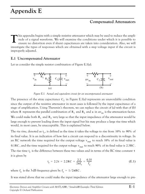
Appendix ECompensated AttenuatorsThis appendix begins with a simple resistive attenuator which may be used to reduce the amplitudeof a signal waveform. We will examine the conditions under which it is possible toensure no distortion even if shunt capacitances are taken into consideration. Also, we willinvestigate the types of responses which are obtained with a step voltage input if the circuit isimproperly adjusted.E.1 Uncompensated AttenuatorLet us consider the simple resistor combination of Figure E.1(a).Rv in R 2 C 2 v outC 2R 1 av in v out( a) ( b)Figure E.1. Actual <strong>and</strong> equivalent circuit for an uncompensated attenuatorThe presence of the stray capacitance C 2 in Figure E.1(a) represents an unavoidable conditionsince the output of the resistive attenuator in most cases is followed by the input capacitance of astage of amplification. Using Thevenin’s theorem, we can replace the circuit of (a) with that of (b)where R represents the parallel combination of R 1 <strong>and</strong> R 2 <strong>and</strong> a in av inis the attenuation factor.We could make both R 1 <strong>and</strong> R 2 very large so that the input impedance of the attenuator would belarge enough to prevent loading down the input signal but his may produce a large rise time whichwould, in most cases, be unacceptable. This is explained below.The rise time, denoted as t r, is defined as the time it takes the voltage to rise from 10% to 90% ofits final value. It is an indication of how fast a circuit can respond to a discontinuity in voltage. Inan RC network the time required for the output voltage v outto reach 10% of its final value is0.1RC , <strong>and</strong> the time required for the output voltage v outto reach 90% of its final value is 2.3RC .The rise time t ris the difference between these two values <strong>and</strong> in terms of the RC time constant τit is given by2.2 0.35t r = 2.2τ = 2.2RC = ---------- = ---------(E.1)2πf c f cwhere f cis the 3-dB frequency given by f c = 1⁄2πRC.It was stated above that we could make the input impedance of the attenuator large enough to pre-<strong>Electronic</strong> <strong>Devices</strong> <strong>and</strong> <strong>Amplifier</strong> <strong>Circuits</strong> with MATLAB® / Simulink® Examples Third EditionCopyright © Orchard PublicationsE−1


