

Electronic Devices and Amplifier Circuits
Electronic Devices and Amplifier Circuits - Orchard Publications
Electronic Devices and Amplifier Circuits - Orchard Publications

Create successful ePaper yourself
Turn your PDF publications into a flip-book with our unique Google optimized e-Paper software.
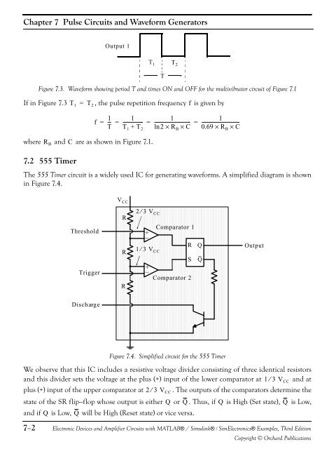
Chapter 7 Pulse <strong>Circuits</strong> <strong>and</strong> Waveform GeneratorsOutput 1T 1 T 2TFigure 7.3. Waveform showing period T <strong>and</strong> times ON <strong>and</strong> OFF for the multivibrator circuit of Figure 7.1If in Figure 7.3 T 1 = T 2 , the pulse repetition frequency f is given byf1 11= -- = ----------------- = ------------------------------- =T T 1 + T 2 ln2×R B × C1---------------------------------0.69 × R B × Cwhere <strong>and</strong> C are as shown in Figure 7.1.R B7.2 555 TimerThe 555 Timer circuit is a widely used IC for generating waveforms. A simplified diagram is shownin Figure 7.4.V CCThresholdR2⁄ 3 V CC+Comparator 1TriggerRR1 3+R⁄ V CC1 3SComparator 2QQOutputDischargeFigure 7.4. Simplified circuit for the 555 TimerWe observe that this IC includes a resistive voltage divider consisting of three identical resistors<strong>and</strong> this divider sets the voltage at the plus (+) input of the lower comparator at ⁄ V CC <strong>and</strong> atplus (+) input of the upper comparator at 2⁄ 3 V CC . The outputs of the comparators determine thestate of the SR flip−flop whose output is either Q or Q . Thus, if Q is High (Set state), Q is Low,<strong>and</strong> if Q is Low, Q will be High (Reset state) or vice versa.7−2<strong>Electronic</strong> <strong>Devices</strong> <strong>and</strong> <strong>Amplifier</strong> <strong>Circuits</strong> with MATLAB® / Simulink® / Sim<strong>Electronic</strong>s® Examples, Third EditionCopyright © Orchard Publications


