

Electronic Devices and Amplifier Circuits
Electronic Devices and Amplifier Circuits - Orchard Publications
Electronic Devices and Amplifier Circuits - Orchard Publications

You also want an ePaper? Increase the reach of your titles
YUMPU automatically turns print PDFs into web optimized ePapers that Google loves.
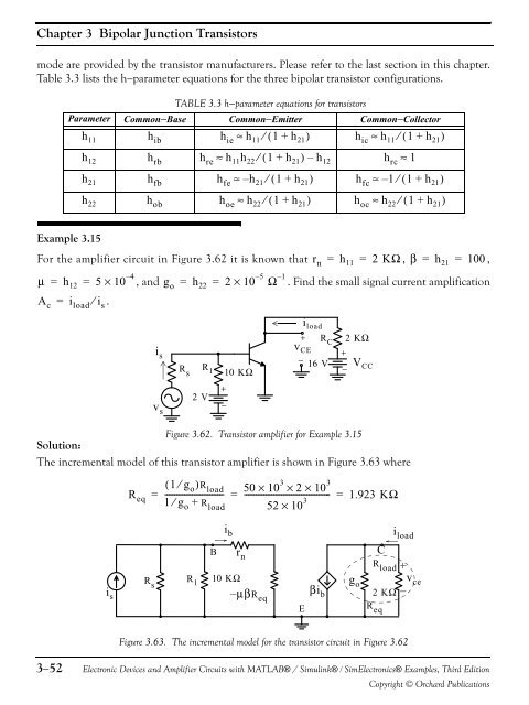
Chapter 3 Bipolar Junction Transistorsmode are provided by the transistor manufacturers. Please refer to the last section in this chapter.Table 3.3 lists the h−parameter equations for the three bipolar transistor configurations.TABLE 3.3 h−parameter equations for transistorsParameter Common−Base Common−Emitter Common−Collectorh 11 h ib h ie ≈ h 11 ⁄ ( 1 + h 21 ) h ic ≈ h 11 ⁄ ( 1 + h 21 )h 12 h rbh re≈ h 11 h 22 ⁄ ( 1 + h 21 ) – h 12 h rc≈ 1h 21 h fb h fe ≈ – h 21 ⁄ ( 1+h 21 ) h fc ≈ – 1⁄( 1 + h 21 )h 22 h ob h oe ≈ h 22 ⁄ ( 1 + h 21 ) h oc ≈ h 22 ⁄ ( 1 + h 21 )Example 3.15For the amplifier circuit in Figure 3.62 it is known that r n = h 11 = 2 KΩ , β = h 21 = 100 ,μ = h 12 = 5 × 10 – 4, <strong>and</strong> g o = h 22 = 2 × 10 – 5Ω – 1. Find the small signal current amplificationA c = i load ⁄ i s .v s+2 V−i sR si load+ R 2 KΩv CCE +−R 16 V V CC1 10 KΩ−Figure 3.62. Transistor amplifier for Example 3.15Solution:The incremental model of this transistor amplifier is shown in Figure 3.63 whereR eq( 1 ⁄ g o )R------------------------------ load 50 × 10 3× 2 × 10 3= = ------------------------------------------- = 1.923 KΩ1 g o +52 × 10 3⁄ R loadi bi loadi sR sR 1B r n10 KΩ–μβR eqEβi bg oCR load2 KΩR eqv ceFigure 3.63. The incremental model for the transistor circuit in Figure 3.623−52<strong>Electronic</strong> <strong>Devices</strong> <strong>and</strong> <strong>Amplifier</strong> <strong>Circuits</strong> with MATLAB® / Simulink® / Sim<strong>Electronic</strong>s® Examples, Third EditionCopyright © Orchard Publications


