

Electronic Devices and Amplifier Circuits
Electronic Devices and Amplifier Circuits - Orchard Publications
Electronic Devices and Amplifier Circuits - Orchard Publications

You also want an ePaper? Increase the reach of your titles
YUMPU automatically turns print PDFs into web optimized ePapers that Google loves.
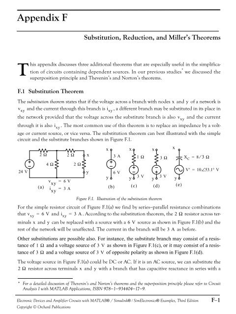
Appendix FSubstitution, Reduction, <strong>and</strong> Miller’s TheoremsThis appendix discusses three additional theorems that are especially useful in the simplificationof circuits containing dependent sources. In our previous studies * we discussed thesuperposition principle <strong>and</strong> Thevenin’s <strong>and</strong> Norton’s theorems.F.1 Substitution TheoremThe substitution theorem states that if the voltage across a branch with nodes x <strong>and</strong> y of a network isv xy<strong>and</strong> the current through this branch is i xy, a different branch may be substituted in its place inthe network provided that the voltage across the substitute branch is also v xy<strong>and</strong> the currentthrough it is also i xy. The most common use of this theorem is to replace an impedance by a voltageor current source, or vice versa. The substitution theorem can best illustrated with the simplecircuit <strong>and</strong> the substitute branches shown in Figure F.1.2 Ω24 V y( a)4 Ω2 Ωv xy= 6 Vi xy= 3 A2 Ωxx x x xy( b)3 A6 V3 V 3 VyFigure F.1. Illustration of the substitution theoremFor the simple resistor circuit of Figure F.1(a) we find by series−parallel resistance combinationsthat v xy = 6 V <strong>and</strong> i xy = 3 A. According to the substitution theorem, the 2 Ω resistor across terminalsx <strong>and</strong> y can be replaced with a source with a 6 V source as shown in Figure F.1(b) <strong>and</strong> therest of the network will be unaffected. The current in the branch will be 3 A as before.Other substitutions are possible also. For instance, the substitute branch may consist of a resistanceof 1 Ω <strong>and</strong> a voltage source of 3 V as shown in Figure F.1(c), or it may consist of a resistanceof 3 Ω <strong>and</strong> a voltage source of 3 V of opposite polarity as shown in Figure F.1(d).The voltage source in Figure F.1(a) could be DC or AC. If it is an AC source, we can substitute the2 Ω resistor across terminals x <strong>and</strong> y with a branch that has capacitive reactance in series with ay( c)1 Ω( d)3 Ω X C = 8 ⁄ 3 Ωy( e)V' = 10∠53.1°V* For a detailed discussion of Thevenin’s <strong>and</strong> Norton’s theorems <strong>and</strong> the superposition principle please refer to CircuitAnalysis I with MATLAB Applications, ISBN 978−1−934404−17−9.<strong>Electronic</strong> <strong>Devices</strong> <strong>and</strong> <strong>Amplifier</strong> <strong>Circuits</strong> with MATLAB® / Simulink® / Sim<strong>Electronic</strong>s® Examples, Third EditionCopyright © Orchard PublicationsF−1


