

Electronic Devices and Amplifier Circuits
Electronic Devices and Amplifier Circuits - Orchard Publications
Electronic Devices and Amplifier Circuits - Orchard Publications

You also want an ePaper? Increase the reach of your titles
YUMPU automatically turns print PDFs into web optimized ePapers that Google loves.
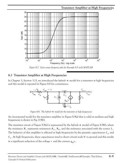
Transistor <strong>Amplifier</strong> at High Frequencies26242220Gain (dB)18161412108610 0 10 1 10 2 10 3 10 4 10 5 10 6Frequency (Hz) - log scaleFigure 8.7. Gain versus frequency plot for Example 8.3 with MATLAB8.3 Transistor <strong>Amplifier</strong> at High FrequenciesIn Chapter 3, Section 3.13, we introduced the hybrid− π model for a transistor at high frequencies<strong>and</strong> this model is repeated in Figure 8.8 for convenience.i b v' be = vBv be r' br be+ −+ C 2C 1−g m vi cr ov ceCEi eFigure 8.8. The hybrid− π model for the transistor at high frequenciesAn incremental model for the transistor amplifier in Figure 8.9(a) that is valid at medium <strong>and</strong> highfrequencies is shown in Fig. 8.9(b).The transistor circuit of Figure 8.9(a) is represented by the hybrid− π model of Figure 8.9(b), wherethe resistance R 1 represents resistances R A , R B , <strong>and</strong> the resistance associated with the source I 1 .The behavior of this amplifier is affected at high frequencies by the parasitic capacitances C e<strong>and</strong>C c. At high frequencies, these capacitances tend to short−circuit node b' to ground <strong>and</strong> this resultsin a significant reduction of the voltage v <strong>and</strong> the current g m v .<strong>Electronic</strong> <strong>Devices</strong> <strong>and</strong> <strong>Amplifier</strong> <strong>Circuits</strong> with MATLAB® / Simulink® / Sim<strong>Electronic</strong>s® Examples, Third EditionCopyright © Orchard Publications8−9


