

Electronic Devices and Amplifier Circuits
Electronic Devices and Amplifier Circuits - Orchard Publications
Electronic Devices and Amplifier Circuits - Orchard Publications

Create successful ePaper yourself
Turn your PDF publications into a flip-book with our unique Google optimized e-Paper software.
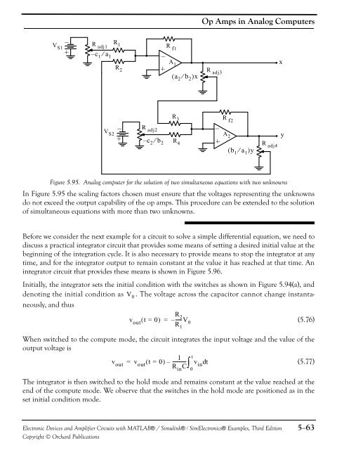
Op Amps in Analog ComputersVR 1S1– c 1 ⁄ a 1V S2R f1xR 2R 3( a 2 ⁄ b 2 )xR adj3R f2– c 2 ⁄ b 2A 1A 2R 4R adj1R adj2R adj4( b 1 ⁄ a 1 )yyFigure 5.95. Analog computer for the solution of two simultaneous equations with two unknownsIn Figure 5.95 the scaling factors chosen must ensure that the voltages representing the unknownsdo not exceed the output capability of the op amps. This procedure can be extended to the solutionof simultaneous equations with more than two unknowns.Before we consider the next example for a circuit to solve a simple differential equation, we need todiscuss a practical integrator circuit that provides some means of setting a desired initial value at thebeginning of the integration cycle. It is also necessary to provide means to stop the integrator at anytime, <strong>and</strong> for the integrator output to remain constant at the value it has reached at that time. Anintegrator circuit that provides these means is shown in Figure 5.96.Initially, the integrator sets the initial condition with the switches as shown in Figure 5.94(a), <strong>and</strong>denoting the initial condition as V 0 . The voltage across the capacitor cannot change instantaneously,<strong>and</strong> thusv out ( t = 0)=R----- 2R 1– V 0(5.76)When switched to the compute mode, the circuit integrates the input voltage <strong>and</strong> the value of theoutput voltage is1 tv out = v out ( t = 0)– ----------- v (5.77)R in Cin dtThe integrator is then switched to the hold mode <strong>and</strong> remains constant at the value reached at theend of the compute mode. We observe that the switches in the hold mode are positioned as in theset initial condition mode.0<strong>Electronic</strong> <strong>Devices</strong> <strong>and</strong> <strong>Amplifier</strong> <strong>Circuits</strong> with MATLAB® / Simulink® / Sim<strong>Electronic</strong>s® Examples, Third EditionCopyright © Orchard Publications5−63


