

Electronic Devices and Amplifier Circuits
Electronic Devices and Amplifier Circuits - Orchard Publications
Electronic Devices and Amplifier Circuits - Orchard Publications

You also want an ePaper? Increase the reach of your titles
YUMPU automatically turns print PDFs into web optimized ePapers that Google loves.
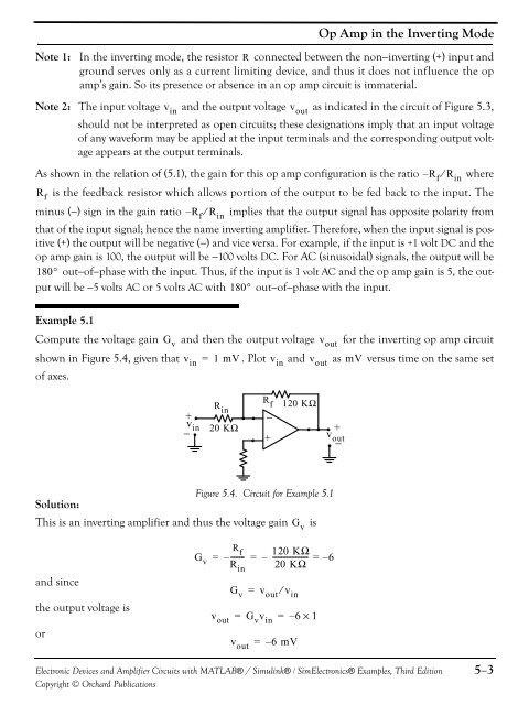
Op Amp in the Inverting ModeNote 1: In the inverting mode, the resistor R connected between the non−inverting (+) input <strong>and</strong>ground serves only as a current limiting device, <strong>and</strong> thus it does not influence the opamp’s gain. So its presence or absence in an op amp circuit is immaterial.Note 2: The input voltage v in<strong>and</strong> the output voltage v outas indicated in the circuit of Figure 5.3,should not be interpreted as open circuits; these designations imply that an input voltageof any waveform may be applied at the input terminals <strong>and</strong> the corresponding output voltageappears at the output terminals.As shown in the relation of (5.1), the gain for this op amp configuration is the ratio – R f ⁄ R inwhereR fis the feedback resistor which allows portion of the output to be fed back to the input. Theminus (−) sign in the gain ratio – R f ⁄ R inimplies that the output signal has opposite polarity fromthat of the input signal; hence the name inverting amplifier. Therefore, when the input signal is positive(+) the output will be negative (−) <strong>and</strong> vice versa. For example, if the input is +1 volt DC <strong>and</strong> theop amp gain is 100, the output will be −100 volts DC. For AC (sinusoidal) signals, the output will be180° out−of−phase with the input. Thus, if the input is 1 volt AC <strong>and</strong> the op amp gain is 5, the outputwill be −5 volts AC or 5 volts AC with 180° out−of−phase with the input.Example 5.1Compute the voltage gain <strong>and</strong> then the output voltage for the inverting op amp circuitshown in Figure 5.4, given that = 1 mV. Plot v in<strong>and</strong> v outas mV versus time on the same setof axes.G vv inv out+v in−R in20 KΩR f−+120 KΩ+v out−Figure 5.4. Circuit for Example 5.1Solution:This is an inverting amplifier <strong>and</strong> thus the voltage gainG vis<strong>and</strong> sincethe output voltage isorG vR f= –------- = –R inG v = v out ⁄ v in120 KΩ-------------------- = – 620 KΩv out = G v v in = – 6×1v out = – 6 mV<strong>Electronic</strong> <strong>Devices</strong> <strong>and</strong> <strong>Amplifier</strong> <strong>Circuits</strong> with MATLAB® / Simulink® / Sim<strong>Electronic</strong>s® Examples, Third EditionCopyright © Orchard Publications5−3


