

Electronic Devices and Amplifier Circuits
Electronic Devices and Amplifier Circuits - Orchard Publications
Electronic Devices and Amplifier Circuits - Orchard Publications

You also want an ePaper? Increase the reach of your titles
YUMPU automatically turns print PDFs into web optimized ePapers that Google loves.
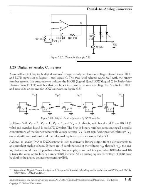
Digital−to−Analog ConvertersV10100 KΩ 15.9 μF 100 KΩ KΩ15.9 μF50 KΩD 1 D 2V outFigure 5.82. Circuit for Example 5.215.23 Digital−to−Analog ConvertersAs we will see in Chapter 6, digital systems * recognize only two levels of voltage referred to as HIGH<strong>and</strong> LOW signals or as logical 1 <strong>and</strong> logical 0. This two−level scheme works well with the binarynumber system. It is customary to indicate the HIGH (logical 1)<strong>and</strong> LOW (logical 0) by Single−Pole−Double−Throw (SPDT) switches that can be set to a positive non−zero voltage like 5 volts for HIGH<strong>and</strong> zero volts or ground for LOW as shown in Figure 5.83.V N V D V C V BV A5 V 5 V 5 V 5 V 5 VFigure 5.83. Digital circuit represented by SPDT switchesIn Figure 5.81 V D = 0 , V C = 1 , V B = 0 , <strong>and</strong> V A = 1 , that is, switches A <strong>and</strong> C are HIGH (5volts) <strong>and</strong> switches B <strong>and</strong> D are LOW (0 volts). The first 16 binary numbers representing all possiblecombinations of the four switches with voltage settings V A (least significant position) through V D(most significant position), <strong>and</strong> their decimal equivalents are shown in Table 5.1.A digital−to−analog (D/A or DAC) converter is used to convert a binary output from a digital system toan equivalent analog voltage. If there are 16 combinations of the voltages V D through V A , the analogdevice should have 16 possible values. For example, since the binary number 1010 (decimal 10)is twice the value of the binary number 0101 (decimal 5), an analog equivalent voltage of 1010 mustbe double the analog voltage representing 0101.* Refer also to Digital Circuit Analysis <strong>and</strong> Design with Simulink Modeling <strong>and</strong> Introduction to CPLDs <strong>and</strong> FPGAs,ISBN 978−1−934404−05−8.<strong>Electronic</strong> <strong>Devices</strong> <strong>and</strong> <strong>Amplifier</strong> <strong>Circuits</strong> with MATLAB® / Simulink® / Sim<strong>Electronic</strong>s® Examples, Third EditionCopyright © Orchard Publications5−51


